In my first article (February 2018), I discussed the three parts of electricity, volts, amps and resistance (ohms). Now we’re going to discuss Digital Multi Meters (DMM) and how one can be used to measure volts, amps and ohms.
DMM Basics
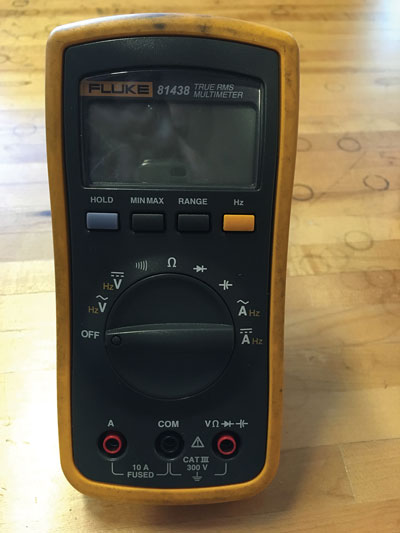
A DMM can come in two forms: an “Auto Ranging Meter” or a “Manual Ranging Meter.” When testing voltage or resistance with an auto-ranging DMM you can simply connect the meter to the source being tested and the meter will find the appropriate range automatically. With a manual-ranging DMM you must select the proper setting using the dial on the front (see Figure 1).

For example, if you wanted to test the resistance of a wheel speed sensor that should have a resistance of about 1,000 ohms, you would have to set the scale on your DMM to the 2,000-Ohm scale. If you checked this sensor in the 200-Ohm scale, your reading would be O.L. (Out of Limits) since the meter is not set to see resistance this high. This could lead to a misdiagnosis of a part.
With an auto-ranging DMM, the meter would automatically find the appropriate scale and give you a reading. For the purposes of the rest of this article we’re going to make all of our tests with an auto-ranging DMM.
There are also several symbols on the front of a meter (see Figure 2); for our purposes we will only focus on five of them:
- Voltage is indicated by a capital V
- Amperage (AKA current) indicated by a capital A
- Resistance (ohms) indicated by the omega symbol (Ω)
- Direct Voltage/Current is indicated by either DC or
- Alternating Voltage/Current is indicated by either AC or ~
Testing Voltage
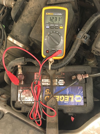
To check for voltage in a circuit you must first put your leads in the proper jacks. This usually means the black lead goes into the black jack marked “COM” and the red lead goes into the red jack that will have a “V” over it.
We then turn the dial on the DMM to the Voltage DC setting and we are ready to test. Now place the black test lead to a known-good ground and place the red lead to the wire or circuit you are testing. Turn the circuit on (if it is not already hot) and your meter will read the voltage being applied at that point (see Figure 3).
Checking Resistance
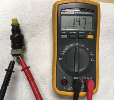
Resistance testing is always done with the power off. The dial on the DMM should be put in the Ω position, the black lead in the COM jack and the red lead into the jack with the Ω over it. When checking a circuit for resistance, the power must be off. When checking the resistance of a load, the component should be disconnected from the circuit (see Figure 4).
Checking Amperage
To check amperage (current flow) in a circuit, we start with the circuit off. The dial on the DMM should be turned to the amperage position, the black lead is left in the COM jack and the red lead is put into the jack with an A over it. The circuit must be somehow disconnected so the leads of the DMM can be put in series with the circuit (see Figure 5).
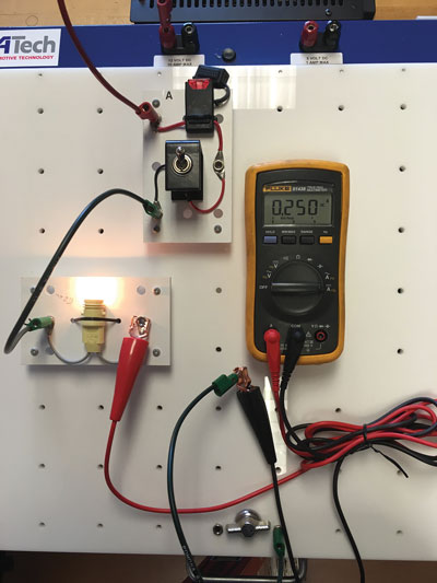
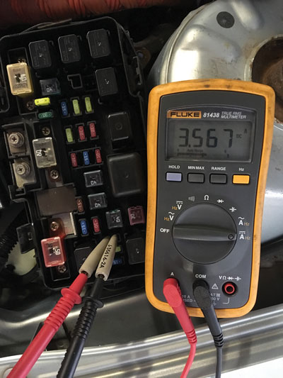
My preference is to do this at the relay/fuse center. If the fuse is 10 amps or less,
I can pull the fuse and put my DMM leads into the fuse slots (see Figure 6). By doing this, the DMM becomes part of the circuit and will display the amount of amperage being used by a load. If the amperage draw exceeds 10 amps, an amp clamp should be used so damage to the meter does not occur.