The following is a guide to troubleshooting diagnostic trouble code (DTC) P2122 on a 2012 Honda CR-V. This code refers to: Accelerator Pedal Position (APP) Sensor ‘A’ Throttle Position Sensor ‘D’ Circuit Low Voltage
Possible causes:
- Faulty Accelerator Pedal Position
- Accelerator Pedal Position harness is open or shorted
- Accelerator Pedal Position circuit has poor electrical connection
- Faulty Powertrain Control Module (PCM)
Possible symptoms:
- Engine Light (or Service Engine Soon Warning Light) is on
- No Accelerator Pedal response
The APP sensor A is part of the electronic throttle control system (ETCS), and it is used to convert the position of the accelerator pedal into electrical signals. Based on these signals, the PCM controls the throttle actuator so that the throttle position agrees with the accelerator pedal position. If the signal voltage from APP sensor A is a set value or less, the PCM detects a malfunction and stores a DTC.
Note: Before you troubleshoot, record all freeze-frame data and any onboard snapshots, and review the general troubleshooting information.
1. Problem verification:
a. Turn the ignition switch to On (II).
b. Check the parameter(s) below with the HDS/aftermarket equivalent:
Signal Threshold
Values/Unit
APP Sensor A Less than 0.2V
Do the current conditions match the threshold?
YES: The failure is duplicated. Go to step 2.
NO: Intermittent failure — the system is OK at this time. Check for poor connections or loose terminals at the APP sensor and the PCM.
2. Determine possible failure area (VCC4 line, others):
a. Turn the ignition switch to Lock (0).
b. Disconnect the APP sensor 6P connector.
c. Turn the ignition switch to On (II).
d. Measure the voltage between test points 1 and 2.
Test condition: IG ON (II)
APP sensor 6P connector: disconnected
Test circuit: VCC4, SG4
Test point 1: APP sensor 6P connector No. 4 (BRN)
Test point 2: APP sensor 6P connector No. 5 (LT BLU)
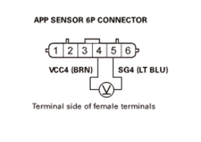
Is there about 5.0V?
YES: Go to step 3.
NO: Go to step 6.
3. Shorted wire check (APS1 line):
a. Turn the ignition switch to Lock (0).
b. Jump the SCS line with the HDS/aftermarket equivalent.
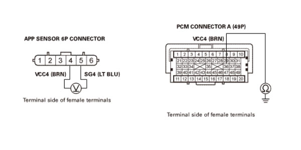
c. Disconnect PCM connector A (49P).
d. Check for continuity between test points 1 and 2.
Test condition: IG LOCK (0)
APP sensor 6P connector: disconnected
PCM connector A (49P): disconnected
Test circuit: APS1
Test point 1: APP sensor 6P connector No. 6 (ORN)
Test point 2: Body ground
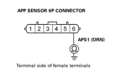
Is there continuity?
YES: Repair a short in the APS1 wire between the PCM (A28) and the APP sensor, then do the repair verification.
NO: The APS1 wire is not shorted. Go to step 4.
4. Open wire check (APS1 line):
a. Connect terminals A and B with a jumper wire.
Terminal A: APP sensor 6P connector No. 6 (ORN)
Terminal B: Body ground
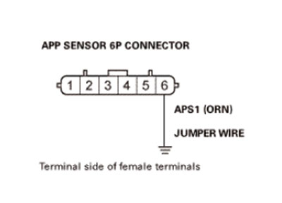
b. Check for continuity between test points 1 and 2.
Test condition: IG LOCK (0)
APP sensor 6P connector: disconnected
APP sensor 6P connector No. 6: jumped to body ground
PCM connector A (49P): disconnected
Test circuit: APS1
Test point 1: PCM connector A (49P) No. 28 (ORN)
Test point 2: Body ground
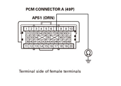
Is there continuity?
YES: The APS1 wire is OK. Go to step 5.
NO: Repair an open in the APS1 wire between the PCM (A28) and the APP sensor, then do the repair verification.
5. PCM internal circuit check:
a. Reconnect PCM connector A (49P).
b. Connect terminals A and B with a jumper wire.
Terminal A: APP sensor 6P connector No. 4 (BRN)
Terminal B: APP sensor 6P connector No. 6 (ORN)
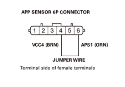
c. Turn the ignition switch to On (II).
d. Check the parameter(s) below with the HDS/aftermarket equivalent:
Signal Threshold
Values/Unit
APP Sensor A Less than 0.2V
Do the current conditions match the threshold?
YES: Update the PCM if it does not have the latest software, or substitute a known-good PCM, then do the repair verification.
NO: Replace the APP sensor, then do the repair verification.
6. Open wire check (VCC4 line):
a. Turn the ignition switch to Lock (0).
b. Jump the SCS line with the HDS/aftermarket equivalent.
c. Disconnect PCM connector A (49P).
d. Connect terminals A and B with a jumper wire.
Terminal A: APP sensor 6P connector No. 4 (BRN)
Terminal B: Body ground
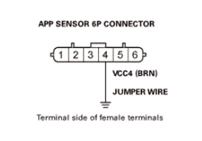
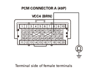
e. Check for continuity between test points 1 and 2.
Test condition: IG LOCK (0)
APP sensor 6P connector: disconnected
APP sensor 6P connector No. 4: jumped to body ground
PCM connector A (49P): disconnected
Test circuit: VCC4
Test point 1: PCM connector A (49P) No. 36 (BRN)
Test point 2: Body ground
Is there continuity?
YES: The VCC4 wire is OK. Update the PCM if it does not have the latest software, or substitute a known-good PCM, then do the repair verification.
NO: Repair an open in the VCC4 wire between the PCM (A36) and the APP sensor, then do the repair verification.
Repair verification:
- Turn the ignition switch to Lock (0).
- Reconnect all connectors.
- Turn the ignition switch to On (II).
- Reset the PCM with the HDS/aftermarket equivalent.
- Do the PCM idle learn procedure.
- Check for pending or confirmed DTCs with the HDS/aftermarket equivalent.
Is DTC P2122 indicated?
YES: Check for poor connections or loose terminals at the APP sensor and the PCM. If the PCM was updated, substitute a known-good PCM, then recheck. If the PCM was substituted, go to step 1.
NO: Troubleshooting is complete. If the PCM was substituted, replace the original PCM. If any other pending or confirmed DTCs are indicated, go to the indicated DTC’s troubleshooting.
Sources: MotoLogic and Engine-Codes.com