Here in the upper part of the West Coast, four-wheeling is a very large part of outdoor recreation. Vehicles of all kinds are taken to the forests and mountains every weekend. There are miles and miles of off-road trails, and organized clubs are available for every make, model and size of 4WD vehicle. Toyota trucks are a very popular platform for every aspect of the sport. Large wheels and tires, pumped engines, lifted and shortened bodies and all sorts of added equipment are the order of the day for a lot of off-road enthusiasts.
Often, the addition of horsepower, or the increase in traction and torque provided by larger-than-normal tires, can lead to failure of the clutch. The size of the clutch is really not an issue here though. Toyota has always supplied a clutch size that will meet just about any need within the normal range of use of these trucks. But heavy off-road use is seldom normal, especially when climbing hills or going over logs. In this article, I’ll cover the steps necessary to replace a clutch on a Toyota 4×4, and give you some tips to help you make sure your customer’s next off-road trip is a successful one.
 PREPARATION
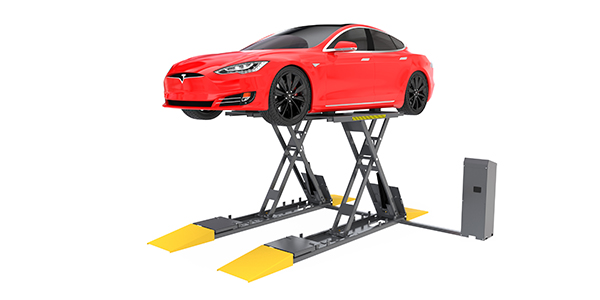
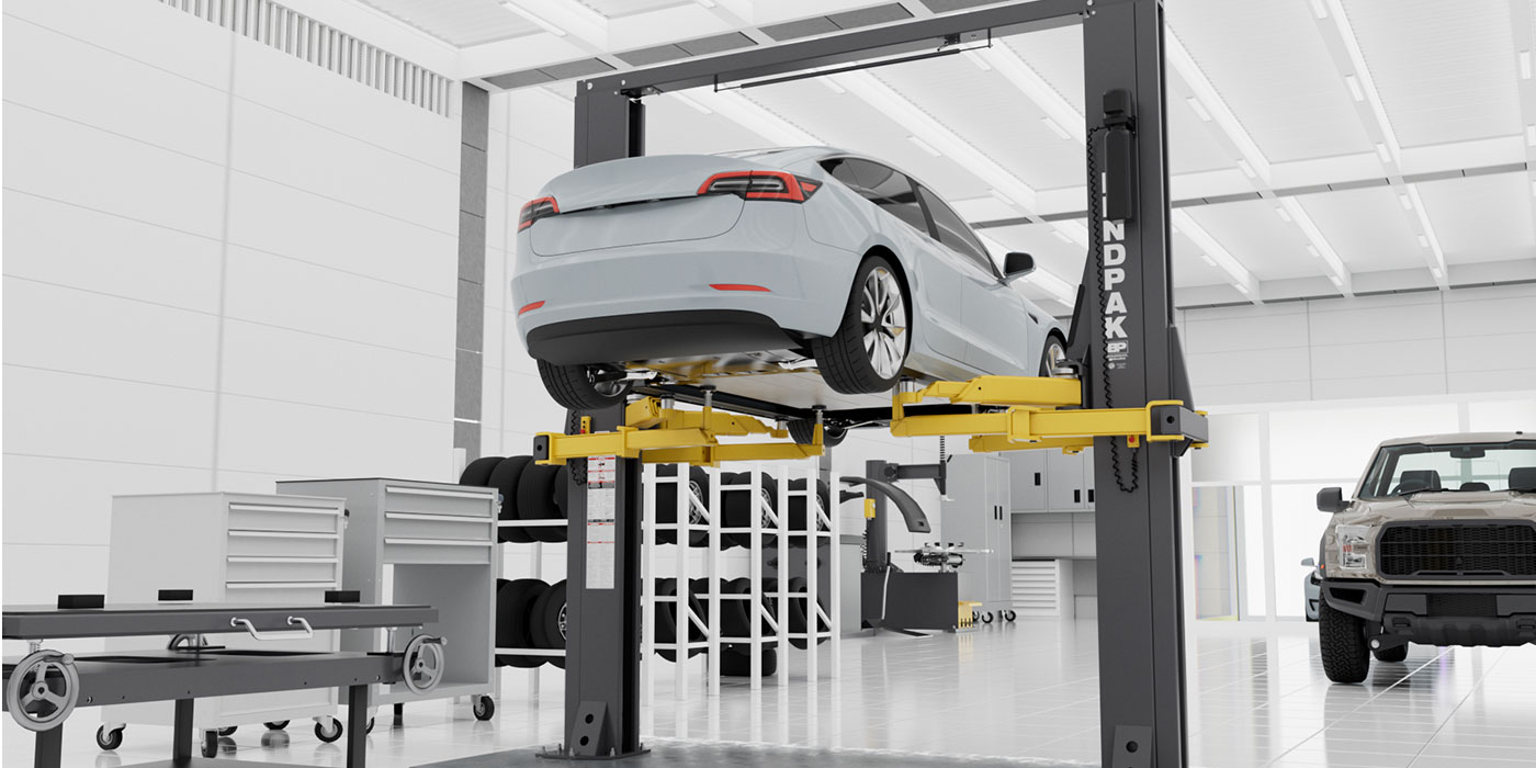
Removing a transmission for repair is always a bit of a challenge on single-post hoists, so if you have a two-post or wheel-lift hoist, it would be a better choice for clutch or transmission repairs. I’m always especially careful to make sure the hoist arms are as far out (front to rear) on the frame as possible to provide a firm, open work area. For long-wheelbase vehicles, an underhoist jack can be put lightly under the rear bumper to provide a more stable lift. Because there will be some pushing and prying to align major components during this repair, the vehicle needs to be secured to prevent mishaps. I know you taller guys need to put the hoist stands up for head clearance; just make sure that the vehicle isn’t going to move around when you’re under it. I’ve seen a truck fall when the hoist stands were not positioned properly, so be sure they are always at opposing angles. A quality transmission jack that can handle the bulk of the transmission and transfer case as a unit is important as well. An underhoist jack can be very useful for positioning the engine angle to line up with the transmission assembly, both for removal and installation.
Remember to wear safety glasses and a dust mask, especially when removing the clutch components. There can still be asbestos in the disc on the older trucks.
The procedures for removing the transmission and transfer case on Toyota models haven’t changed much in the last 20 to 30 years. Unlike some other brands of small 4×4 trucks, there is no need to remove parts of the suspension, and there’s a removable crossmember for easier removal of the drivetrain (See Photo 1). Both four-cylinder and V6 models have the same basic components, so the procedures are very similar. Early models with solid front axles have even less intrusion of the suspension components.
Photos 1 through 6
TRANSMISSION AND TRANSFER CASE REMOVAL
I know that the removal of the transmission assembly isn’t “rocket science.” I also know that some components are often removed that don’t need to be. Taking off as few items as necessary saves time and money. As always, a well thought-out plan will speed the work and make the end result more satisfactory.
Any major repair should start with disconnecting the battery. Because the starter will need to be at least unbolted, the chance that the power lead might short out and cause damage is reason enough. On most four-cylinder models, the upper starter nut is easier to reach from the top, so I usually remove it before putting the truck in the air. There really isn’t anything else that needs to be done on the ground.
With the truck in the air, disconnect the front driveshaft at the differential end. The rear driveshaft is unbolted at the transfer case output (see Photo 2). Even with a two-piece rear driveshaft, the shaft can just be tied out of the way to one side or the other to provide enough space for the removal. You do not need to drain the transmission or transfer case.
On six-cylinder trucks, you may need to remove at least one of the headpipes, depending on the year, because there isn’t enough room to squeeze the transmission past the exhaust. Remove the nuts at the manifold flanges, and unbolt it at the catalytic converter. Remember to disconnect the O2 sensor on trucks with the sensor in the headpipe. You will also need to remove the bracket holding the headpipe to the bellhousing, on both four- and six-cylinder models.
Disconnect the electrical wiring to the transmission and transfer case at the multi-plugs clipped to the side of the tranny and then tie them out of the way. Remove the speedometer cable or disconnect the speed sensor wiring.
Remove the bolts holding the clutch slave cylinder to the bellhousing (see Photo 3). Unless it’s leaking, don’t open the bleeder, or remove the hose; just push it forward to release it from the clutch fork and tie it to the side. The hose may still be attached to the bracket at the lower starter mounting, so move it to get the cylinder out of the way. Now is the time to remove the lower starter bolt.
Continue removing the bellhousing bolts at the lower part of the bellhousing. To gain extra working room on models with a sway bar, remove the bolts at the frame brackets (see Photo 4) and let the bar hang from the links. That will provide a lot of additional space.
If you want to fight with the upper bellhousing bolts at this point, be my guest. I would put the transmission jack under the transmission/transfer case crossmember. To secure the trans to the jack, I use a ratcheting tie-down strap, and wrap the front driveshaft together with the trans and t-case. Remove the bolts holding the crossmember to the frame (see Photo 5) and slightly lower the assembly. By doing so, the upper trans bolts are easier to see and remove.
With the transmission lowered, you can also reach up and remove the bolts holding the two shifter housings to the top of both gearboxes (see Photo 6). Doing this from under the truck saves a lot of time otherwise spent trying to remove the shifter from the top. After a few of these jobs, this becomes an easy procedure – both to take apart and put back together. Push the shift levers up into the boots as far as possible to prevent them from getting in the way of removing the transmission.
Depending on the model, you can now put an underhoist jack lightly under the front of the engine (with the skid plate removed) or put a block of wood between the crossmember and oil pan. This will hold the engine at an angle that will make removal and installation less of a chore. Now you can remove the remaining bellhousing bolts.
While monitoring the angle of the engine and transmission, the two can be separated. You may need to pry slightly to start the separation, but if you need more than gentle persuasion, something is not right. The culprit is likely the angles between components, which will put a bind on the input shaft and pilot bearing. On some model years, there are hidden bolts through the rear engine plate from the front side of the bellhousing. Straightening this out now will make reinstallation a lot smoother. Once the transmission is back far enough for the transmission input shaft to clear the clutch, you can lower it down.
CLUTCH REPLACEMENT
Use water or parts cleaner to wet the clutch components, since there may still be some asbestos fibers in some older clutches.
Check the condition of the pressure plate release fingers and the release bearing for signs of excessive wear. This may give you a chance to nail the cause of a premature clutch failure, and instruct the car owner how to avoid the same problem in the future. (That far left pedal is not a foot rest!) Remove the six pressure plate bolts and, while holding onto the pressure plate, pry the plate off of the alignment dowels along with the disc.
A little detective work here may also tell a tale of failure. Check the disc for uneven contact with the pressure plate or flywheel; oil, mud or dirt on the contact surfaces; signs of overheating; or slippage and abuse (broken damper springs usually indicate the clutch is being used as a brake). Performing this inspection will give you a better understanding of how to approach the normal questions that should be asked when dealing with clutch failure.
Inspect the flywheel, looking for cracks and scorched spots. Determine if resurfacing is needed by checking the specs for a step or flat surface. On just about all Toyota trucks, the step is 0.020 inches or 0.500 mm between the pressure plate mounting surface and the higher disc contact surface. Measure using a straight edge and feeler gauges. Measure the step at several different points around the diameter of the flywheel. Toyota indicates runout up to about 0.010-inch is acceptable, but ideally runout should be zero.
We have our own flywheel grinder in our shop, so we turn just about any flywheel that is removed. You’ll need to remove the alignment pins, and take your time to get a nice, smooth surface on the flywheel to prevent grabbing or chattering.
If there is any hint of leakage at the rear main seal, replace it.
Inspect the back of the engine for any signs of other leaks. On V6 engines especially, there are core plugs that can leak coolant at the back of the block.
With the flywheel refreshed and new clutch in hand, compare the replacement clutch, release bearing and disc with the originals to make sure they are the same. The important points are the height of the pressure plate and the “fit” of the release bearing on the carrier. Also, test-fit the disc onto the transmission input shaft to be sure the spline count and size are correct. You will need to remove the release bearing carrier from the old bearing, and press on the new bearing in the correct direction before lubricating the carrier and sliding it onto the input shaft housing and clipping it in place. When applying grease to the inner recess of the bearing carrier, keep in mind less grease is better. Otherwise, grease can get scraped onto the new clutch by release bearing movement.
You will want to replace the pilot bearing in the crankshaft if there is any tightness or roughness. Any sign of rust in the pilot bearing recess is a sure sign of imminent failure. Sometimes, these can be difficult to remove. We have found that a slide hammer-type puller usually does the trick but, on occasion, we have had to resort to an oldtimer’s trick of hydraulic removal. This is done by filling the recess in the crank behind the bearing with grease, and then using a tight-fitting alignment tool, socket or piece of round stock (a bolt will do in a pinch) with a hammer to force the bearing out. Then clean the pilot bearing hole and install the new bearing.
When reinstalling the flywheel, make sure you use either thread-locking compound or a sealer on the bolt threads as the bolts go through the crankshaft flange into the crankcase. Torque the flywheel bolts in a crosswise pattern to specs while holding the flywheel. Remember that turning the flywheel to tighten the bolts turns the engine over backward, and a loose timing belt or chain just might slip.
Make sure the surfaces of the flywheel and pressure plate are clean and dry, then use an alignment tool to set the disc and pressure plate into position on the flywheel, aligning the holes in the plate with the dowel pins.
Lightly tighten the pressure plate bolts in a crosswise pattern in several steps, checking that the alignment tool will still move freely after each step. Lubricate the splines of the transmission input shaft and the hub of the disc with either high-temp grease or moly grease. Again, just a light coating is needed to prevent the splines from binding.
After the final tightening (usually no more than 15 ft.-lbs. is needed on the pressure plate bolts), again, make sure the alignment tool will move freely. This will make reinstalling the drivetrain a snap.
FINISHING UP
From here you just need to reinstall the transmission and transfer case in reverse order of removal. Getting the proper alignment of the engine and transmission should make the install easy. If you need to use more than a little force, back off and see what the problem is, or you just might seriously shorten the life of the new clutch. If you have a few of old bolts of the correct size and thread, make a couple of guide pins and install them at opposite points to guide the transmission into place.
Perform a longer-than-normal road test just to help correctly break in the parts and make sure the clutch and transmission are operating properly. Like brake repairs, the initial few miles can make or break a good repair. Instruct the owner of the vehicle not to abuse the clutch for a few days to prevent shortening the service life. On vehicles with oversize tires, make sure the customer also understands that the clutch is potentially the weakest link in the drivetrain, so it should be treated mostly as a drivetrain disconnect, not slipped or used as a brake.
Larry has more than 30 years of off-road driving experience. At one time, he was a regional director for the Pacific Northwest Four-Wheel-Drive Association, with more than 50 clubs in his region. His time in four-wheeling included racing, sand drags, rock climbing and even two trips to work in the pits at the Mint 400 off-road race.