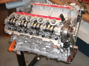
 Choosing the “right” camshaft is not only the cornerstone of building a performance engine, but also its centerpiece.
Choosing a cam can give anyone a headache – especially if they choose the wrong cam for a given application. There’s a lot of science involved in cam selection, so keep reading and we’ll help you wade through the details.
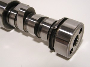
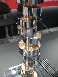
A camshaft is nothing more than a cast iron or steel shaft with a series of lobes strategically placed along its length. Each lobe opens and closes a valve by moving a lifter, pushrod and rocker arm, or in the case of an overhead cam engine by moving a cam follower or direct valve action.
The size, shape and placement of the lobes on the camshaft determines valve timing, compression and the engine’s breathing characteristics, which in turn determines the engine’s performance potential and the rpm range where the engine will make the most power and torque.
Choosing the “right” camshaft, therefore, is not only the cornerstone of building a performance engine but also its centerpiece. The cam makes the engine and essentially determines all of the other parts that should be chosen to build the engine (cylinder heads, pistons, valvetrain, intake and exhaust manifolds, and carburetion).
Most camshaft manufacturers offer a wide range of off-the-shelf grinds that have been developed for specific applications. The secret to choosing a cam that will deliver the kind of performance you want is to figure out the rpm range where the engine should make the most power, and then choose a cam that will match the breathing characteristics of the cylinder heads, intake and exhaust manifolds, weight and gearing of the vehicle the engine is going into.
 If your building a big stroker motor for a ProStock drag car with an aftermarket 500 to 600 cubic inch block and cylinder heads with fist-sized ports that flow over 500 cfm at .900˝ valve lift, such an engine obviously needs a big cam with lots of valve lift, duration and overlap.
On the other hand, if you’re building a small block street performance engine that’s going into a daily driver with an automatic transmission and stock gearing, you’ll want a cam that delivers good drivability with plenty of low to mid-range torque and throttle response. You’ll also want to choose cylinder heads that have relatively small intake runner volumes for good air velocity and throttle response at low- to mid-range rpm, a split-plenum 180-degree hi-rise intake manifold and properly sized carburetor.
Don’t Overcam Your Work
The biggest mistake many engine builders make is to overcam an engine. Using a cam that has too much valve lift, too much duration and/or too much valve overlap for the application can have negative consequences.
Everybody likes big numbers, but if the cam specs don’t really match the engine you’re building or the application the engine is going into, you’ll end up with an engine that underperforms and fails to meet your customer’s expectations.
Keep Your Eye on Valve Lift
Increasing valve lift opens the valve further so more air/fuel mixture or exhaust can flow past the valve. Valve lift is increased by using taller lobes on the camshaft and/or higher ratio rocker arms. Increasing valve lift improves airflow up to a point, so you want more lift in a performance cam. But airflow eventually peaks out because of restrictions in the cylinder head, intake or exhaust system. Increasing valve lift beyond this point is pointless because there’s nothing more to be gained.
There are also physical limits as to how far the valves can be opened before it creates interference problems between the valves and pistons, between the valve spring retainers and the tops of the valve guides, and between the coils of the valve springs.
 Modifications can be made to increase clearances (such as cutting larger valve recesses into the tops of the pistons, reducing the height of the valve guides and/or lowering the spring seats), but eventually the limit is reached beyond which no further increases in valve lift are physically possible.
Many cams today have “asymmetrical” grinds that use different profiles for the upside and downside ramps on the cam lobes, as well as different lobes for the intake and exhaust valves.
So the only way to increase airflow further is to hold the valves open longer (increase duration) by opening the valves sooner and closing them later, and/or by improving the scavenging effect of the exhaust to pull air/fuel mixture through the combustion chamber by increasing valve overlap. There’s a lot of science that goes into determining optimum valve lift, and how quickly the valves open and close. Ideally, you want a fast acting cam that opens and closes the valves quickly to maximize airflow. You also want the cam to reach peak lift as quickly as possible, although airflow at mid-lift actually has more of an impact on total airflow because it happens twice during each valve cycle (once as the valve opens and again as it closes).
Consequently, you want cam lobes that open the valves quickly, hold the valves open when airflow is greatest, and then close the valves quickly to minimize compression losses. With flat tappet cams, the curvature of the ramp on the side (flank) of the lobe that opens the valve can’t be too steep, otherwise the lifter may dig into the ramp. Likewise, on the closing side of the lobe, the curvature can’t be too steep, otherwise the lifter may not follow the lobe and bounce on its way back down.
Roller cams are much better in this respect because a roller on the bottom of a lifter can follow a more radical lobe profile. A roller cam can open and close the valves faster for more total airflow with the same lift and duration.
Valve Timing Issues
Valve timing includes the points at which the intake valves open and when they close, and when the exhaust valves open and when they close. Of these four timing events, intake valve closing actually has the greatest impact on now much power a particular camshaft will make. If the intake valve closes too soon, the cylinder may not fill completely during its intake stroke.
Holding the intake vale open longer allows more airflow into the cylinder – up to a point. If the intake valve remains open too long past the point where the piston has reached and passed bottom dead center, the upward motion of the piston can start to reverse airflow and push air back out of the intake port.
The point at which the exhaust valve opens has the second greatest impact on performance. If the exhaust valve opens too soon, cylinder pressure may be lost before it can complete its work. If the exhaust valve is opened too late during the exhaust stroke, it increases the pumping effort required to push the exhaust out of the cylinder.
The closing of the exhaust valve and the opening of the intake valve, by comparison, have the least impact on performance. If the exhaust valve closes too quickly, some exhaust may remain in the cylinder and dilute the incoming air/fuel mixture during the following intake stroke. Holding the valve open longer (even as the intake valve starts to open) creates a scavenging effect that helps pull air through the cylinder into the exhaust, but you don’t want too much valve overlap as this can rob some of the air/fuel mixture that would otherwise remain in the cylinder (it also increases exhaust emissions).
The opening of the intake valve has to occur early enough so the cylinder has time to fill with air/fuel mixture, but if it starts to open too soon (before top dead center), you can get reversionary airflow back into the intake manifold.
The point at which the intake and exhaust valves open and close is determined by the ramps on the cam lobes. As soon as the lifter or follower reaches the point where the ramp starts from the lobe base circle, the valvetrain begins to move and starts to open the valve. The opening point may be measured at a specified amount of lift (such as .004˝ or .050˝) and listed as lasting so many degrees of crankshaft rotation.
For example, a typical street performance cam might have a listed duration of 224 degrees for the intake and exhaust valves measured at .050˝ of lift, with a maximum lift of .470˝ (with stock 1.5 ratio rocker arms).
The lobe separation between the peak lift points of the intake and exhaust valves might be 110 degrees. Street cams and cams that are designed to produce more low to mid-range torque typically have less overlap and more lobe separation, while cams that are designed more for maximum high speed power have more overlap and less lobe separation.
Confusing Calculations
Comparing one cam grind to another can be tricky because camshaft suppliers often measure their cam specifications differently. If duration is measured at .004˝ of lift rather than .050˝ of lift, it inflates the numbers and makes the cam appear bigger.
Consequently, it’s important to note at what point lift is actually measured when comparing advertised camshaft duration specs. Generally speaking, the longer the duration the higher the rpm range where the cam makes power. Short duration cams are good for low speed torque and throttle response while long duration cams are best or high revving engines that need to make lots of top end power.
Cams with durations in the 195 to 210 degree range (measured at .050˝ cam lift) are usually considered best for stock unmodified engines and those with computerized engine controls. Once you go beyond 210 to 220 degrees of duration, intake vacuum starts to drop. This upsets idle quality and affects the operation of computerized engine control systems.
Performance cams typically have durations ranging from 220 up to 280 degrees or more. The longer the duration, the rougher the idle and the higher the cam’s power range on the rpm scale. A cam with a duration of 240 degrees of higher will typically produce the most power from 3,500 to 7,000 rpm.
But there’s more to camshaft selection than lift and duration. Cams from two different manufacturers may have identical lift and duration specs, but have considerably different performance characteristics because of the shape of the lobes. A lot of development work has gone into revamping lobe profiles in recent years to optimize performance, and many cam suppliers have introduced new product lines that reflect these improvements.
Some cam lobes may have steeper or shallower ramps to change the velocity at which the valves open and close. A fast opening rate is great as long as the valve springs and valvetrain are stiff enough to handle it. Closing the valves quickly is also good, but not good if the valves close so abruptly that they bounce when they hit their seats or the lifters can follow the down ramp of the cam lobe.
Many cams today also have “asymmetrical” grinds that use different profiles for the upside and downside ramps on the cam lobes, as well as different lobes for the intake and exhaust valves. Some cams even feature slightly different grinds for each of the engine’s cylinders, depending on where the cylinder is positioned in the engine block.
The end cylinders on a V8 with a single carburetor manifold typically benefit with a little more valve duration for the end cylinders to equalize airflow through the intake manifold. It’s a trick that NASCAR has used for years and is now available in some off-the-shelf product lines.
Choose Wisely
Picking a cam at random out of a catalog or on a website that has dozens or even hundreds of different grinds listed can be a daunting task. The cam you choose may or may not deliver the results you are looking for, so it pays to read all of the fine print for each grind and to study the recommendations. The cam supplier may say a particular works best with certain cylinder head, piston and intake system combinations.
Various software programs are also available that can help you choose a particular cam based on the information you enter into the program. The software recommends a cam that best matches the information you have entered, and will even plot simulated dyno horsepower and torque curves for the engine you are building. Though not 100 percent accurate, these programs do a pretty good job of steering you to the right cam.
The best approach, however, is to work directly with a cam supplier when choosing a cam. Most cam suppliers are more than happy to assist you in the cam selection process.
They can provide you with a highly detailed questionnaire you can fill in to narrow down all of the engine specifics so a cam can be chosen that will deliver the best all-round performance for what you are building. Details include everything from engine displacement, cylinder heads, compression ratio, intake and exhaust systems, naturally aspirated or boosted, manual or automatic transmission, torque converter stall speed, manual transmission gear ratios, differential ratio and tire size to what kind of cam/lifter setup you want (flat tappet, roller, solid or hydraulic) to info on how the engine will be used (street, street/strip, circle track, drag racing, road racing, off-roading, pulling, towing, RV or marine) to the year/make/model and weight of the vehicle the engine is going into.
If you’re looking for an edge over the competition, you might opt to have a custom cam ground for your engine.
This may require even more detailed information such as airflow numbers for each increment of valve lift through the cylinder heads, rod length, stroke, brands of pistons, rods or other parts, and so on.
The more information you can provide the cam supplier, the better they can match a custom cam to your engine.
Some cam companies have even used data recording to optimize a custom cam for a customer. They hook up a data logger to record engine rpm while a car is on the race track, then analyze engine speeds down the straights and into and out of the corners to determine where the engine really needs to make the most power. A cam grind is then chosen that maximizes engine power out in the rpm range where it really needs it. A bigger cam might make more total power, but if the engine seldom revs high enough to take advantage of that extra power it’s more cam than the engine really needs.
It’s better to have a cam that really works in the optimum rpm range, than to choose one that makes big numbers but doesn’t win races on the race track.
Article courtesy of ENGINE BUILDER magazine.


