 By Matt Dixon, Assistant Professor, SIU Carbondale
For late-model vehicles, the norm is one ignition coil per cylinder, commonly known as coil on plug. The task of providing voltage potential to each spark plug is performed so reliably that it’s easy to take for granted.
An underhood comparison of a variety of vehicles, however, reveals there are subtle differences among coils. For example, each individual coil may be connected to two, three or four control wires.
This varying attribute among coils prompted my investigation and testing. I wanted to determine how each version is controlled and monitored. I also wanted to find out which tools are best suited to test each version.
This article will convey my findings.
Each wired version of coil commonly contains a battery voltage power feed.
The path connecting battery voltage to the coils can vary considerably. Several vehicle manufacturers utilize one or more relays with possible varying control logic.
Others provide a more direct fused run/start feed from the ignition switch. Relays and fuses make good testing access points as many vehicles have obstacles including intake manifolds that prevent easy physical access to all of the coils. 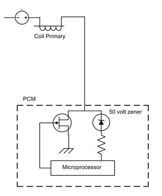
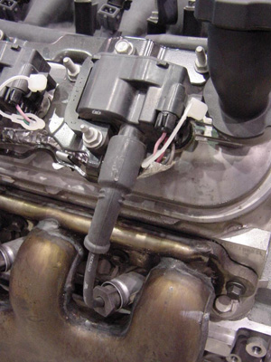
The two-wire coil versions can be found on Ford and Chrysler products. The PCM directly controls the pulsed ground dwell to each primary coil. Because of direct coil primary circuit access, these coils provide flexibility in diagnostic testing.
Primary ignition waveforms can be accessed at each individual coil or at the PCM, whichever is easier.
While connecting a scope to the ignition primary, an attenuator may be necessary to protect the scope from high voltage inductive kick. The voltage kick within the primary pattern is relevant to the PCM on-board diagnostics.
A zener diode placed in parallel to the PCM internal switching electronics is rated at a specific zener voltage.
See Figure 1.
When the transistor interrupts current flow, the resulting inductive voltage crosses the zener to provide a confirmation pulse of coil firing to the microprocessor. An absence of kick, say from an open or an unplugged coil, results in a P035x coil control circuit code.
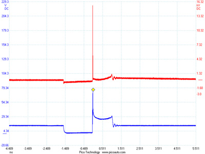 The primary pattern closely mirrors the secondary pattern (see Figure 2) and comparison between cylinders provides valuable diagnostic reference.
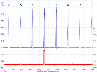
Chrysler PCMs monitor primary pattern burn time and can potentially set coil ionization fault codes. Ford, along with some other manufacturers, commands multiple coil firings per cylinder event.
This is commonly known as “multi-strike” and is performed at lower engine rpm to ensure low hydrocarbon emissions.
See Figure 3.
Primary ignition current can be measured with an inductive amp clamp and, in this case, can be measured around either coil wire.
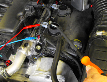
The use of a fused jumper wire placed across the applicable ignition system relay cavities or in place of an ignition system fuse provides quick and easy comparison between all cylinders. Secondary patterns can be obtained with the use of an inductive wand adapter held in varying coil proximities. 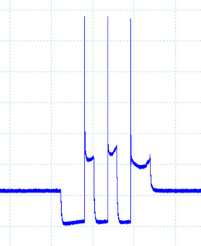
See Figure 4.
Depending on accessibility, secondary patterns can also be obtained by removing the coil and installing a spark plug wire along with a conventional secondary pickup scope adapter.
Two-Wire Coils
Two-wire coil primary resistance can be measured with an ohmmeter. Resistance is typically under an ohm. Secondary resistance may be 10,000 or more ohms.
Secondary resistance may be measured depending on if the coil is equipped with an internal high voltage zener diode placed between the secondary winding and the plug terminal.
If equipped, the diode serves to prevent the secondary coil from ionizing the plug gap during initial dwell.
 A DVOM placed on “diode check” can be used to check the secondary winding connection on diode-equipped coils.
Two-wire systems typically have one or more capacitors placed in parallel to the coils’ collective power supply. The capacitor(s) serve to speed switching and protect the PCM’s internals.
These capacitors are usually less than one microfarad and can also be checked with a DVOM.
Three-Wire Coils
Three-wire coils are commonly found on Nissans, Hondas, Mitsubishis, some General Motors and several other makes.
These coils connect to 12-volt power, chassis ground and a command pulse signal from the PCM. There usually isn’t a connection between coil circuitry and the bolt eyelet ground.
Exceptions to this are Delphi coils found on Chevrolet Trailblazers, which connect the chassis ground terminal to the bolt eyelet.
 For three-wire coils, the PCM determines the dwell and timing but does so indirectly. The PCM provides a pulse command, which signals the electronics within each coil to switch.
The duration of the command pulse equals the dwell time of the coil.
See Figure 5.
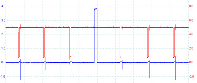
I tested several Nissan, Acura and Mitsubishi vehicles and was surprised to find that a coil connector could be unplugged and not trigger coil-related trouble codes.
 This was confirmed on multiple trips. Eventually, a misfire code would set and illuminate the MIL but without hint that a coil was to blame. The command pulse is worth checking using a lab scope. The majority of vehicles use a 5-volt pulse; however, a few use full charging voltage.
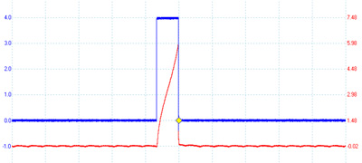
If a coil is unplugged, thereby eliminating electrical load, the signal will be full value, typically 5 volts. However, on a connected and loaded circuit, the voltage is closer to 4 volts. Pay attention to the amplitude and shape of the signals as coil issues can be revealed in the pattern.
See Figure 6.
Because internal electronics control primary coil switching, primary resistance cannot be directly measured.
Depending upon internal controls, secondary resistance may not be measured either.
With resistance checks and coil primary voltage patterns unavailable, primary current measurement is a good choice.
Again, the best spot is a common relay or fuse that feeds all coils.
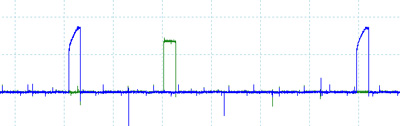
See Figure 7.
Peak current values and patterns differ between vehicles, so comparison between cylinders is the applicable measure.
 Coil secondary voltage patterns can also be measured as mentioned regarding two-wire coils.
Four-Wire Coils
There are two popular flavors of four-wire ignition coils. The first can be found on Toyotas.
Three of the wires are power, chassis ground and PCM command signal, just like the previously mentioned three-wire coil.
The fourth wire is a diagnostic circuit known as “IGF” and is run in parallel with all of the ignition coils. The PCM provides a 5-volt bias voltage on this circuit.
Each coil has integral diagnostic detection electronics, and when a coil successfully fires, it briefly pulses the IGF circuit to ground as a confirmation pulse to the PCM.
To test this system, I removed the chassis ground wire from an ignition coil and monitored both the command pulse and diagnostic circuit.
Sure enough, the command pulse was provided, but without diagnostic ground pulse for that cylinder.
See Figure 8.
The PCM quickly set a coil diagnostic code.
The second version of four-wire coil is found on some General Motors products. These coils utilize power, chassis ground, a PCM command signal known as “IC” and a fourth wire known as low reference. Low reference is a treated, “cleaner” ground that is sourced through the PCM.
From measuring current on each circuit, it appears that low reference is used for the electronics within the coil while chassis ground handles the greater load of ignition primary coil current. On some versions, the bolt eyelet is electrically connected to the coil chassis ground terminal.
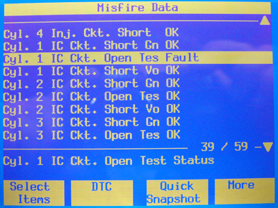
The “IC” command pulse circuit is monitored by the PCM for opens and shorts to voltage and/or ground. For example, in the case of an unplugged coil, the command pulse circuit unloaded reaches a full 5 volts. When connected, the pulse is close to 4 volts. The PCM will quickly set a P035xx code based on improper IC circuit voltage amplitude. This circuit can also be monitored using the factory scan tool.
See Figure 9.
Under normal operation, low reference and chassis grounds are electrically separated. Resistance measured between these circuits with the coil isolated is over 50,000 ohms. Interestingly, there appears a failsafe ability within the coil to utilize one or the other circuit if necessary.
This was determined by removing the chassis ground, low reference and bolt eyelet ground each one at a time. The coil operated flawlessly with no codes using only low reference or chassis ground. The Pontiac Solstice I tested was able to function with both chassis ground and low reference wires pulled out of the coil connector, using only the bolt eyelet chassis ground.
These findings illustrate that although all coil on plug systems have the same job task no matter how many wires, they each have their own quirks. They can be monitored for trouble codes using at least three different strategies and, in some cases, are not monitored.
DVOMs and scan tools are of assistance only with some coils. Coil primary and secondary patterns can be helpful depending on the coil type, physical access and adaptors available. Collecting a scope trace of PCM command pulses is of value on three- and four-wire coils. The test that worked on all coil versions was primary current measurement using an inductive amp clamp and scope.
This measurement provides verification of both pulse command and solid electrical connections. It also provides valuable comparisons between cylinders. The next time one of these normally reliable systems fails in its task, hopefully you’ll be ready to succeed in yours.