Nothing is more frustrating than diagnosing an intermittent cranking, no-start complaint with no diagnostic trouble codes (DTCs) and no apparent failure pattern. Much of the time, the cranking, no-start complaint lies with a failing crankshaft or camshaft position sensor. Many of these failures can be heat-related and might require several warm-up cycles to duplicate.
So, in some instances, it’s more economical to replace a crankshaft or camshaft position sensor than it is to spend hours trying to capture the suspected failure on a scan tool or lab scope.
In other instances, the failure lies within the wiring harness or, in some cases, the ignition control module (ICM) or the powertrain control module (PCM). Whatever the case, a technician needs a good working knowledge of how the camshaft and crankshaft position sensors work together to create a fuel injection and spark cycle.
CRANKSHAFT POSITION SENSORS (CKP)
In brief, the crankshaft position sensor (CKP) indicates when each piston reaches top dead center (TDC). To time the spark event, the PCM calculates the angular position of the crankshaft connecting rod journal in relation to TDC. To illustrate, the PCM might time the spark event at 10° before top dead center (BTDC) on the compression stroke. See Photo 1. 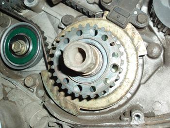
The CKP also detects cylinder misfires on post-1996 OBD II engines by measuring very small variations in crankshaft speed. For example, the crankshaft decelerates as a cylinder approaches TDC on compression stroke. After combustion, the crankshaft accelerates on the power stroke until about 90° after top dead center (ATDC), when cylinder pressure is expended and the angularity of the connecting rod diminishes. When this very predictable deceleration and acceleration pattern is disrupted on a continuing basis, the PCM stores a misfire trouble code for that cylinder.
CAMSHAFT POSITION SENSORS (CMP)
Because the crankshaft on a four-cycle engine rotates at twice the speed of the camshaft, each cylinder fires on alternate strokes. In most applications, the CMP determines when number-one cylinder reaches TDC on compression stroke. With that said, some engines don’t incorporate a CMP into their operating strategy. Instead, the PCM alternates base timing 180° during cranking and, when an increase in cranking speed is detected, the PCM identifies that position as TDC compression stroke. See Photo 2.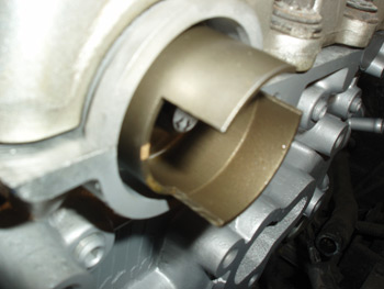
The basic function of the CMP, in most applications, is to determine when fuel should be injected into the cylinder. In most applications, the injector sprays fuel into the intake port at about 26° ATDC when the intake valve is nearing maximum lift.
DISTRIBUTOR IGNITIONS
Some import distributors might incorporate a crankshaft, camshaft and TDC position sensor to allow the sequential fuel injection system to sense TDC compression stroke. Because the integrated camshaft position sensor can be used to time the fuel injection, it’s important to install the number-one spark plug wire in its specified position and to install the distributor and rotor in their specified positions. See Photo 3.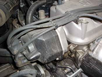
MAGNETIC RELUCTANCE POSITION SENSORS
The magnetic reluctance sensor is basically a single wire wrapped around a permanent magnet, with each end of the wire representing a positive or negative pole. As a rotating ferrous reluctor tooth passes the sensor, it generates an alternating current (AC) signal to the PCM.
In Photo 4, notice that the “analog” signal varies between approximately 0.8 positive volts and 0.2 negative volts. Because AC voltage can be displayed more accurately on a lab scope than a voltmeter, it’s easier to track the voltage as it alternates between positive and negative. In this case, the PCM “reads” TDC when the sensor signal crosses the zero volt line. The accuracy of the reluctance sensor varies slightly due to the voltage switching from positive to negative at slightly different points along the “zero” line. The accuracy of the reluctance sensor can also be affected by the sensor magnet attracting particles of ferrous material from clutch linings or wearing parts. 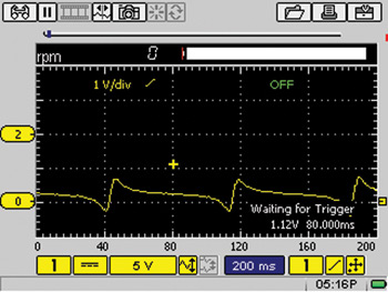
In most applications, the reluctor for the number-one cylinder is slightly modified to provide a “signature” waveform indicating to the PCM when that cylinder reaches TDC. When diagnosing a magnetic reluctance sensor, it’s extremely important to remember that voltage output or amplitude depends very much on the air gap between the sensor tip and reluctor and the speed of the reluctor.
HALL EFFECT POSITION SENSORS
Hall effect sensors are generally three-wire sensors that produce a square-wave digital signal that is sent to the ICM or PCM. See Photo 5.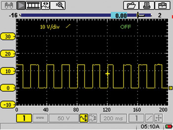
Since Hall effect sensors are produced in many different configurations, suffice it to say that the Hall effect sensor acts as an electric switch that requires an outside power source and a ground to produce the square-wave, on-off pattern. Unlike magnetic reluctance sensors, Hall effect sensors don’t rely on shaft speed to generate a signal.
CKP QUICK TESTING
Scan tools provide the best non-invasive method for diagnosing a cranking, no-start condition. If, for example, engine rpm or speed is displayed during cranking, it’s obvious that the CKP is producing a valid signal. In other cases, the software in the PCM or in the scan tool might not allow the engine speed to be displayed as the engine is cranked.
Another quick, non-invasive test for CKP activity is to connect a voltmeter to the B- side of the ignition coil. If the voltage pulls down from B+ during cranking, the CKP is triggering the ignition module or PCM. If the CKP isn’t triggering spark, the fault might lie with the CKP, ICM or PCM circuits.
CAMSHAFT TIMING SENSORS
In addition to the CMP, most engines equipped with variable camshaft timing incorporate a camshaft timing sensor that indicates the degree of advance or retard being adjusted into the camshaft. Don’t confuse the two because a defective timing sensor generally shouldn’t cause a cranking, no-start complaint and should only store a diagnostic trouble code if it fails.
CMP QUICK TESTING
While some PCMs won’t fire the fuel injectors without a CMP signal, other PCMs adopt a default strategy for firing the fuel injectors if the CMP signal is erratic or missing. In most cases, if the engine has spark, but the fuel injectors aren’t triggering, the CMP signal is missing. See Photo 6.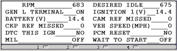
DO YOUR HOMEWORK
Before attempting to diagnose CKP and CMP circuits with a voltmeter or lab scope, try to understand how the system works by having the required wiring schematics on hand. To illustrate, most CKP circuits are wired directly to the PCM.
But, if the ignition takes place through an ICM, the CKP is normally wired directly to the module.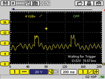
Some ICMs receive a digital signal from a Hall effect CKP sensor and relay that signal to the PCM. Other ICMs convert the analog signal from a reluctance-type CKP sensor to a digital signal before relaying it to the PCM. Once the engine has started, the PCM advances spark by modifying the CKP signal and returning it to the ICM as an electronic spark timing signal.
Here’s an interesting analog or sine wave I captured that 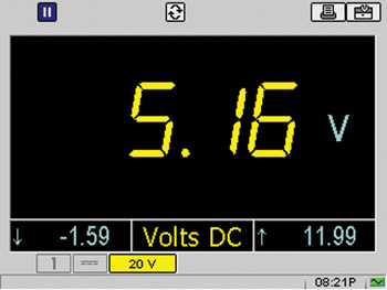 includes the signature signal. See Photo 7. The EST signal sent from the ICM to the PCM is equally as bad. See Photo 8.
Needless to say, the CKP signal from the reluctor-type sensor is floating well above zero volts, which indicates that the ICM might have a bad ground. See Photo 9.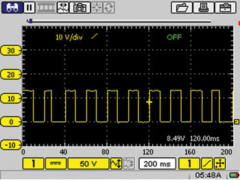
PHYSICAL INSPECTIONS
After preliminary testing, the next step in diagnosing intermittent crankshaft and camshaft position sensor performance is to physically inspect them for loose, chafed or broken wires, loose connectors or loose mounting screws, or indications of damage.
Next, inspect the sensor itself for indications of swelling or cranking in the plastic.
Last, inspect the reluctor or Hall effect shutter for damage or looseness on the shaft. If no other failure conditions are found in the wiring or at the sensor or PCM, it’s entirely appropriate to replace either the CKP or CMP to remedy an intermittent, no-cranking complaint.