This month’s Diagnostic Dilemma: 1999 Dodge Dakota, 5.2-liter engine, automatic transmission, four-wheel drive, 250,000 miles.
Complaint: Engine intermittently stalls after 20-30 minutes of driving time. No diagnostic trouble codes recovered. Client shop reports that engine randomly loses ignition and fuel injector pulse and occasionally loses communication with the scan tool. Black tape covers the “check engine” and “ABS” lights.

Diagnosing intermittent stalling complaints is a challenging experience for any diagnostic technician because any number of electrical and mechanical failures can cause an engine to intermittently stall. Most of us immediately narrow this laundry list of potential failures down to the most common few, which include components like the crankshaft position sensor and electric fuel pump.
In this case, my client shop had replaced the fuel pump earlier because it consistently failed to produce fuel pressure. After replacing the fuel pump, the Dakota developed an intermittent stalling complaint that would occur after about 20-30 minutes of driving time. Since late summer is the busy part of the season in our area, the client shop called me to help locate the source of the intermittent stalling complaint.
The Common Elements
Let’s form a strategy for solving this month’s Diagnostic Dilemma by analyzing the various elements of the case.
1) The stalling complaint was intermittent;
2) The stall required at least 20-30 minutes of drive time before it would occur;
3) The ignition coils and fuel injectors would fail to pulse when the stall occurred; and
4) The scan tool would occasionally lose communication.
The constant in this case was the 20-30 minutes of driving time required to cause the failure. This is always a major clue because components like distributor pick-ups, ignition modules, power train control modules (PCMs) and crankshaft position sensors often require that amount of time to reach operating temperature.
Next, the ignition coil and fuel injectors were losing pulse, which might indicate crankshaft position sensor failure. Lastly, the shop’s scan tool losing communication with the PCM was an issue, which could also be caused by a faulty diagnostic link connector (DLC) cable or scan tool. So that was not an issue at this time.
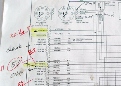
To determine the common elements of a case, I printed an engine performance electrical schematic. In many cases, I tape multiple pages together to help trace various circuits. This helps familiarize me with the basic circuitry and to make my own highlights and notations on the operation of various circuits. These annotated schematics also provide a quick reference for pin-testing the PCM and the Power Distribution Center (PDC).
Since it powers the ignition and injector circuits, the auto shut down (ASD) relay deserves particular attention. According to the schematic, the primary side of the ASD relay is powered from the ignition switch through a junction block equipped with a 10-amp fuse. Current flows from the junction box to the ASD relay’s primary solenoid coil. When the ignition is turned on, the PCM is activated through the key-on circuit, as are the ASD and fuel pump relay primary, ignition coil and fuel injector circuits. But the ASD relay operates only when its primary circuit is pulled to ground by the PCM. Obviously, the ASD relay circuit is a primary suspect in this intermittent stalling complaint.
Unraveling the Data
We’ve all heard about making decisions “in the fog of war.” The same can be said of making decisions “in the fog of diagnosis” because, while we have some of the facts, we don’t have all of the facts. My immediate diagnostic strategy was to collect the rest of the facts by connecting my own scan tool to evaluate the intermittent no-communication problem and to collect codes and data. The codes included a P0443 evaporative failure code, which was irrelevant to our stalling problem. Next was a more significant P1678 DTC, indicating, according to the scan tool, that the mechanical instrument cluster wasn’t receiving bus communication messages. Polling the various on-board modules indicated a glaring “Body Module Fault” in the body control module and a number of two-digit flash codes in the ABS module.
OK, we know we’re losing the ASD relay and now we have some very relevant bus communications DTCS.
Diagnostic Scenarios
The ABS module had been replaced with a used module that might not fit this particular VIN. Although the ABS fuse had been removed because the ABS pump wouldn’t deactivate, the module was evidently still active on the bus communications circuit. Perhaps the ABS module was pulling down the bus circuit, perhaps not. But a bus communications problem doesn’t adequately explain the malfunction in the ASD relay circuit. Nevertheless, when I entered Chrysler’s bi-directional Automatic Test Mode (ATM) to diagnose the instrument cluster, all the gauges activated when commanded.
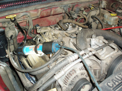
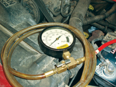
My next step was to install a relay circuit tester attachment under the ASD relay, which allowed me to test the relay’s primary power, ground and B+ output to the ignition coil and fuel injectors. At that time, I noticed that the primary for an aftermarket relay had been spliced into the power distribution center (PDC) wiring. Next, I connected a fuel pump pressure tester so I could keep an eye on the fuel pump and pump relay activity.
Back to the Scan Tool
With my underhood diagnostics in place, it was time to start the engine and record scan tool data. Sure enough, after about 30 minutes of run time, the engine stalled. The fuel pressure gauge indicated specified pressure, so I tested the ASD test jumper attachment to see if the PCM was pulling the primary circuit to ground. With B+ voltage present at both primary terminals, it was obvious that the PCM wasn’t pulling the ASD primary circuit to ground during cranking.
Then my scan tool lost communication. More ominously, a bright green “no bus” message appeared in the odometer display. A quick polling of all modules indicated that all modules were reporting except the PCM.
Quickly, I disconnected the scan tool from the DLC and tested the No. 16 port for B+ (present), No. 4 port for ground (present, using a test light), No. 5 port for ground (present, using a test light) and, most important, the No. 3 and No. 11 ports for the presence of the required +2.5, -2.5 voltage at the Chrysler Collision Detection (CCD) bus communications signal ports (not present). The system was behaving erratically and the values were changing very quickly, so I didn’t check for activity at the serial command interface (SCI) ports, which allows the scan tool to communicate with the PCM and the transmission control module (TCM) where applicable. The No. 2 port is the programmable communications interface (PCI), which allows communication with the body control module (BCM) where applicable.
Also apparent was the intermittent lack of fuel level, coolant temperature and oil pressure gauge activity on the instrument panel (IP). Going back to our schematics, it’s important to note that all three gauges report directly to the PCM and from the PCM to the instrument cluster.