Every once in a while, I see the topic of a diagnostic check sheet come up on the International Automotive Technician’s Network (iATN) or other industry media. Most often, the question is asked by a shop owner or service writer who is trying to simplify his life by devising a “canned” step-by-step approach to solving various electronic diagnostic problems. Although a canned procedure is a good place to start, it’s not a sure-fire way to solving electronic problems because, 1) we’re generally seeing fewer occurrences of pattern failures in modern vehicles, 2) we’re now dealing with networked systems that share information via bus communications links, and 3) most important, nobody can predict the number of twists and turns that a specific diagnostic procedure can take.
With that said, I’ve always taken a methodical approach to solving electronic diagnostic problems by using a procedure rather than a diagnostic checklist. This procedure includes thoroughly interviewing the customer, learning how the system in question works, checking the basics and building a diagnostic strategy. The details of any procedure will obviously vary according to application, but this basic framework should provide a positive approach to solving difficult electronic diagnostic problems.
Case In Point
This month’s Diagnostic Dilemma perfectly illustrates how a well-developed procedure solved a recent case study involving an intermittent transmission failure complaint on a 1994 Plymouth Voyager equipped with the 3.3L engine. 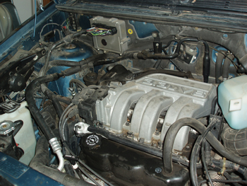 According the owner, the automatic transmission would default to second gear after an initial warm-up drive of about six miles followed by a 10-minute heat-soak with the ignition switch off. The problem could be solved by turning the key off to “reset” the computer and waiting 10 minutes. After a reset, the transmission might perform perfectly for weeks, which is why no other shops in the area wanted to touch the problem.
As I advised the owner, the difficulty of duplicating the problem not only made the actual diagnosis more challenging, but also made it nearly impossible to verify the completed repair. And it was with this disclaimer that I agreed to pursue the problem. Fortunately, time wasn’t a problem and the owner was willing to spend what it took to repair the vehicle because, although the Voyager had 250,000 miles on the odometer, it was very well maintained and served well as general utility vehicle.
 According to its service records, the transmission had been replaced at 168,000 miles. After the second-gear default first appeared, our local transmission shop retrieved a diagnostic trouble code (DTC) 42, which indicated an electrical failure in the 2-4 shift valve circuit. With that bit of information, they “chased” the failure into the winter months, replacing the 2-4 shift solenoid, overdrive solenoid and transmission wiring connector. After the transmission shop exhausted its resources trying to solve what, at best, could be described as a random failure, the owner was referred to me.
Interviewing the Customer
In journalism school, a student is always taught to find the “who, what, when, where and why” of a story. If I were to write a diagnostic check sheet, “who, what, when and where” is how I would begin. What makes this case study interesting was that the lady who owned the van had taken auto mechanics in high school and therefore had a basic understanding of mechanical procedures. So, during our initial phone conversation, I asked her to assemble all of her service records.
During our first interview, she not only presented the service records and owner’s manual, but also produced an OE repair manual for the Voyager. I also had her take me for a test drive with my scan tool attached. I confirmed that the transmission control module (TCM) was communicating correctly, that the DTC 42 was still present, and that the mechanical part of the transmission worked perfectly. She also told me that the failure never occurred in cold weather, but occurred more frequently in warm weather. So much for the “who, what, when and where” of the problem. The “why” part was now up to me.
Gathering a Systems Knowledge
The hardest part of being a diagnostic technician is understanding how a system works (systems knowledge). As in any tough diagnostic case, most of us can spend hours studying wiring diagrams and diagnostic charts before we understand how an especially difficult intermittent failure complaint might occur. The fact also is that any shop should include research time in their basic diagnostic charge, since it is a necessary function of the diagnostic process.
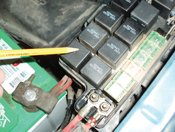
In this application, the transmission is controlled by a separate TCM. Like many later systems, the TCM shares information, such as vehicle speed and throttle position, with the engine control module (ECM). The TCM receives key-on voltage from the ignition switch via a 10-amp fuse #16 located in the instrument panel (I/P) fuse box. The #16 fuse also powers the ECM and several other electronic devices. The TCM receives battery voltage for its keep-alive memory from the ignition off discharge (IDO) 15-amp fuse located in the underhood power distribution center (PDC). The IDO fuse is identified by a bright yellow fuse holder that allows the vehicle owner to temporarily disconnect the fuse to prevent battery drain via the ECM and TCM during long periods of storage. The #12 fuse located in the underhood PDC provides B+ to the TCM relay. Because that fuse wasn’t included in any available wiring diagrams, I had to “reverse engineer” that function by testing all of the TCM circuits with the fuse alternately installed and removed.
As a routine part of any diagnostic procedure, I log into my hotline database to check for any pattern failures and technical service bulletins addressing the initial complaint. In this case, the database indicated that the TCM relay caused the majority of DTC 42 problems. The last items I checked were the enabling criteria for DTC 42 covered in the OE shop manual, which turns out to be a “voltage spike” that occurs when the 2-4 shift solenoid engages. If the TCM didn’t “see” the voltage spike, it would store the DTC 42. So much for gathering systems knowledge, at least for the moment.
Checking the Basics
Checking the basics means that I test the battery, starter and alternator to ensure that the heart of the electrical system is working correctly. To illustrate, a weak battery can erase the adaptive memories on many older Chrysler products including the adaptive memories associated with fuel control and occasionally the adaptive memories that Chrysler uses to compensate for clutch and band wear in their transmissions. More than once I’ve solved a cold-start driveability or cold-start transmission shift quality complaint by simply replacing the battery.
 The next step in any diagnostic check list is to go through the power and ground systems. In this case, one of the B- cables is grounded to the engine and the other to the body. The body ground was corroded, so I cleaned it just to eliminate the possibility of a temperature-sensitive grounding problem. Because this vintage of Plymouth didn’t use weather-pack connectors on its underhood wiring connections, I removed the TCM connector, cleaned the hardened anti-corrosion grease from the terminals, checked the drag on the connector pins, and re-greased and re-installed the connector. Although cleaning and inspecting connectors sounds like extra work, it had paid off just a few weeks before when solving an intermittent transmission shifting complaint on a ‘94 Dodge Diesel. At this point, I had assembled vital information by interviewing the customer, gathering a systems knowledge and checking the basics.
Building a Diagnostic Strategy
The next step in my diagnostic procedure is to build an effective diagnostic strategy that will reveal why the DTC 42 was so dependent upon ambient temperature. Going back to systems knowledge, the enable criteria indicated that the TCM would confirm the 2-4 shift by looking for a voltage spike in the 2-4 shift solenoid circuit. The question, of course, is how to determine when the TCM is grounding the 2-4 solenoid circuit.
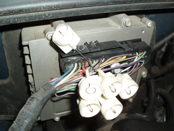
Obviously, since the TCM is pulling the circuit to ground through a resistance provided by the 2-4 shift solenoid, the voltage would be reduced on TCM pin #59 when the 2-4 shift solenoid was activated. To measure that voltage drop, I attached a small alligator clip to one end of a 6’ length of 18-gauge insulated wire and a small loop terminal to the other end. 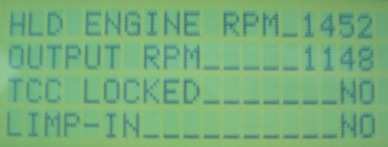 When connected to the 2-4 solenoid terminal at the TCM, this wire allowed me to monitor the 2-4 circuit through a DVOM connected to the receiving end of the wire during a test drive. In addition, I connected my old Snap-on MT 2500 scan tool to indicate the gear and torque converter clutch engagements. In this case, I preferred the MT 2500 because it has a thumb-wheel scroll, which is easier to use during a test drive.
With that done, I waited until ambient air temperature reached about 70° F. and then drove the vehicle eight miles to thoroughly warm up the transmission oil and to monitor transmission performance. The voltage on pin #11 would drop from about 13.8 charging volts to about 10.5 volts when the 2-4 shift solenoid was activated, which indicated that the 2-4 circuit was a pulse-modulated circuit. The DVOM’s min/max feature indicated that the voltage would momentarily drop to about 7.0V, which appeared to indicate a potential circuit problem. The transmission worked perfectly and, after returning to the shop, I parked the Voyager as described by the customer for about 10 minutes. After waiting 10 minutes, the TCM immediately shifted to a default position during the second road test, which meant that the transmission remained in intermediate gear.
Returning to the shop, I kept the engine running and immediately tested the TCM’s surface temperature, which was 84° F, which in my opinion, shouldn’t have caused a heat-related problem. On the other hand, the KOER voltage from terminal #16 in the I/P fuse box to the TCM terminal #11 was only 8.4 volts. Obviously, when the TCM senses a failure in its electrical system, it immediately defaults to second gear by discontinuing power to the transmission solenoids. Going back to the wiring schematic, fuse #16 in the I/P fuse box is powered directly from the ignition switch. With the engine still running, I jiggled the fuse just enough to restore B+ voltage to TCM pin #11.
Through nearly 20 years and 250,000 miles of use, the pins on fuse #16 had obviously developed enough electrical resistance to affect TCM functions. Had I visually inspected fuse #16, I would have dismissed terminal corrosion as a problem. But, by carefully following a thorough diagnostic procedure, I had found a “smoking gun” that evidently was causing the intermittent shift control problem. As a precaution, I replaced all of the fuses supplying the TCM with voltage. In addition, I replaced the ASD and the TCM relays, both of which are wearing parts. The most important aspect of the fuse issue is that a very mysterious problem can be caused by a relatively simple failure. Forty miles of driving under various conditions led me to believe that the problem was solved, which it wasn’t.
Three Weeks Later
Of course, the phone rings and I’m graciously informed by the owner that the problem had not only reappeared, but had manifested itself by suddenly down-shifting to second gear at highway speeds. Here again, the difficulty with this diagnosis was duplicating the problem. Thanks to the problem being temperature sensitive, I had originally suspected a problem with the TCM. But, in the real world, finding a TCM for this vintage of vehicle can be difficult and expensive. So it wasn’t an option that I wanted to pursue until the evidence confirmed the need for replacement.
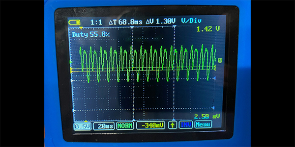
At this point, I resurrected an old industrial lab scope I’ve had for many years that uses two horizontal buttons to adjust time base and two vertical buttons to adjust amplitude, which makes it easier to adjust during a test drive. Thanks again to old technology, the waveform confirmed that the 2-4 solenoid is indeed a pulse-modulated circuit. Although I could never get the transmission to fail, I did see some irregularities in the waveform indicating that the TCM’s 2-4 solenoid driver might be causing a very random failure of the 2-4 shift solenoid circuit. 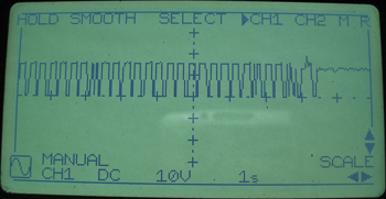
Fortunately, I have a very persistent parts lady who actually found four of these modules on the back shelf of an East Coast ignition parts warehouse. Due to an intervening holiday, it took about a week for the remanufactured TCM to arrive. After re-inspecting the TCM and transmission wiring harness for defects, I replaced the transmission control module. As of this writing, the ‘94 Voyager has been on the road for over two months and the phone hasn’t rung yet. The “moral” of this story is that, while a diagnostic check sheet might be a good place to start, it can’t predict the ultimate destination of any diagnostic journey.