e I live high in the Colorado mountains, loss of power complaints are relatively common and, in most cases, can be confirmed by test-driving the vehicle up one of the mountainous inclines in my area.
While the complaint was readily verifiable, the actual cause wasn’t as obvious. But the symptom of a no up-shift condition with the transmission indicated that the engine wasn’t pumping air as efficiently as it should. 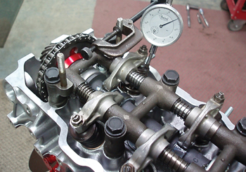
The mass air flow (MAF) sensor was indicating slightly above 57 grams per second (gps) air flow at about 4,300 rpm. Air flow should have been well above 100 gps.
The fact is, air flow is an intricate process that shouldn’t be taken for granted. A slight restriction caused by a mechanical malfunction in an engine’s induction or exhaust system can make subtle, but well-defined differences in how the powertrain operates. In this case, the vehicle ran well until it down-shifted. The only way the driver could get it to up-shift was to reduce throttle.
Conventional Air Flow
Before we diagnose air flow problems, let’s look at how air actually flows through a naturally aspirated engine. Crankpin angle is critical because the air entering the cylinder doesn’t achieve maximum velocity until the crankpin approaches 45° after top dead center (ATDC). Most of the air flow into the cylinder should therefore occur somewhere between 45° and 135° ATDC.
To calculate the duration of any intake valve timing event, add 180° to the intake opening and closing time. For example, if an intake valve opens at 10° before top dead center (BTDC) and closes at 20° after bottom dead center (ABDC), the duration of the valve timing event is 210°. Exhaust timing follows a similar calculation. 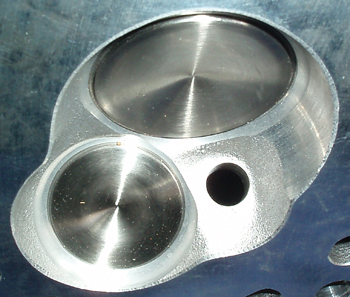
Volumetric Efficiency
Although some automotive enthusiast publications like to express volumetric efficiency as “horsepower per cubic inch,” that definition is irrelevant for diagnostics. For diagnostics, we need to evaluate how completely the cylinder fills with air at a sea-level air pressure of 14.5 pounds per square inch. While cranking at WOT, an engine comes very close to filling its cylinder with air. This would be very close to 100% volumetric efficiency.
As the engine starts, the throttle plate closes to idle speed, thereby restricting air flow into the engine. At closed-throttle, an engine has a very low volumetric efficiency and a very high pressure differential between manifold and atmospheric pressure.
At a WOT governed speed of 2,000 rpm, the pressure differential between intake and atmospheric values drops to nearly zero because the only restriction to air flow would be the throttle plate diameter.
At 2,000 rpm WOT, volumetric efficiency can drop to about 80% on conventional engines simply because the physical size of the intake and exhaust valves and the timing of the valve events tend to restrict air flow at higher engine speeds.
Volumetric efficiency obviously varies among engine designs. At one extreme, we have the lawn mower engine and at the other, we have the supercharged racing engine. 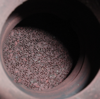
The Intake Valve
The column of air contained within the intake port and manifold runner has inertia, which means that it tends to remain at rest or remain in motion. The column of air contained within an intake port must also constantly accelerate and decelerate in relation to the opening and closing of the intake valve.
Opening the intake valve slightly before the piston reaches TDC can increase high-speed volumetric efficiency.
See Photo 2.
By the time that the piston reaches TDC, the intake valve is beginning to achieve an “effective lift,” which allows the air in the intake port to begin accelerating into the cylinder even as the piston approaches TDC. This cylinder filling effect is further increased by leaving the exhaust valve open, which is described under the exhaust valve section of this text.
To further increase high-speed volumetric efficiency, the intake valve can stay open well after bottom dead center because, once accelerated, the column of air passing through the intake valve into the cylinder tends to remain in motion.
The inertia of this column of air allows the cylinder to continue filling even as the piston begins traveling upward on the compression stroke. Most important, the higher the air velocity in the intake port, the sooner we can open the intake valve and the later we can close it.
The Exhaust Valve
Going back to crankpin angle, much of the combustion gas pressure contained within the cylinder is spent by the time the crankpin passes between 45° and 90° ATDC on power stroke. When the crankpin passes 90° ATDC, the piston is generating very little downward pressure on the crankpin.
To enhance volumetric efficiency, engine designers begin opening the exhaust valve well before BDC to relieve gas pressure built up in the cylinder during combustion. As the piston passes BDC and begins ascending on the exhaust stroke, the flow of the exhaust gasses is restricted by the exhaust valve size and exhaust port configuration.
See Photo 3.
So the exit velocity of the exhaust gasses through the exhaust port and manifold runner can become extremely high.
Performance camshafts take advantage of extremely high exhaust gas velocities by keeping the exhaust valve open ATDC. Due to the high velocity of the exhaust gas passing through the exhaust port at high engine speeds, a slight vacuum or pressure differential is created in the engine cylinder.
Since the intake valve opens slightly BTDC, this pressure differential or “vacuum” helps accelerate the flow of intake air into the engine’s cylinders.
The degrees of engine rotation in which the exhaust and intake valves simultaneously remain open are called valve timing overlap. In contrast to naturally aspirated engines, valve timing duration and valve timing overlap are reduced on supercharged or turbocharged engines. 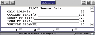
Variable Camshaft Timing
Modern engines incorporate variable camshaft timing to further improve the volumetric efficiency of an engine. Manufacturers advance the valve timing to improve low-speed power and retard the camshaft timing to increase high-speed power.
Dual overhead camshaft engines coupled with computer controls expand the opportunities to change valve overlap to further increase low-speed torque or increase high-speed power. While I won’t dwell on the complexities of variable valve timing, keep in mind that most of these systems use a camshaft position sensor and a valve timing sensor to monitor valve timing and to store a diagnostic trouble code in the PCM’s diagnostic memory if the variable timing system fails.
Tuned Intake Manifolds
I previously mentioned that the velocity of the air flow through the intake port is a critical aspect of valve timing. Engineers have actually reduced the cross-sectional size of intake ports to increase air flow velocity on modern designs. Engineers have also increased air velocity by reducing sharp bends in the intake ports and manifold runners.
 Another method of increasing air flow and volumetric efficiency is to utilize the pressure wave that develops in an intake port when the intake valve closes. At low engine speeds and port velocities, this pressure wave is more readily contained in a long intake port. At higher engine speeds, a short port more efficiently utilizes this pressure wave. Most auto manufacturers have therefore introduced “tuned” intake manifolds that optimize low- and high-speed engine torque by changing the effective length of the intake ports as the engine accelerates.
Horsepower and Torque
In brief, an engine produces maximum foot-pounds of torque at maximum volumetric efficiency. But remember that torque is a static value measured in foot-pounds. In contrast, horsepower is a calculated value combining foot-pounds of torque and time. One horsepower is therefore equal to 550 ft.-lbs. of work done per second of time.
Given the same torque output, a crankshaft spinning at 6,000 rpm will perform twice as much work as a crankshaft spinning at 3,000 rpm. Torque output is reduced once the intake system begins to restrict air flow into the engine and thus reduce volumetric efficiency. So, while the torque value begins to decline with volumetric efficiency, the engine’s capacity to do work continues to increase with speed.
 Basic Diagnostics
While many advanced diagnostic technicians have devised their own methods of measuring air flow through an engine, let’s first master some basic methods of evaluating air flow and volumetric efficiency. Remember that valve timing and air flow velocity are a delicate balance. Any mechanical malfunction that interferes with air flow velocity through the intake or exhaust ports reduces volumetric efficiency and power output.
Air flow through an engine is generally affected by intake air restrictions, valve timing restrictions and exhaust system restrictions. Intake air restriction is generally caused by clogged air intake screens, clogged air filters and collapsed air inlet ducting. Because MAF sensors simply report air flow, the PCM uses MAF input to calculate air/fuel ratios. The air/fuel ratio will therefore not change due to an intake air restriction.
Diagnosing incorrect valve timing can be complicated because an engine can be a dual as well as a single overhead camshaft design and because just one bank of a V-block engine can be affected. But the diagnostics can be simplified on single camshaft designs by remembering that advanced valve timing generally increases intake manifold vacuum and low-speed engine torque.
Exhaust restriction is more difficult to assess because exhaust restriction gradually increases as the catalytic converter becomes contaminated and, in some cases, begins to disintegrate.
See Photo 4.
At some point in its service life, exhaust restriction through the catalytic converter begins to affect volumetric efficiency. Due to differences in camshaft and intake port design, some engines are less affected by exhaust restriction than others, so it’s hard to establish definitive standards for measuring exhaust restriction.
Scan Tool Diagnostics
Because most modern engines use the MAF sensor to sense engine load, one symptom of restricted air flow is that the calculated load displayed on the scan tool is reduced well below its normal values. The engine load calculation is basically the PCM mathematically comparing the air flow measured by the MAF with the throttle opening and engine speed. During this road test, our calculated load was only 55% at WOT, 4,540 engine rpm, which is indicative of an air flow restriction.
See Photo 5.
A low calculated load at WOT is indicative of restricted air flow because, in most cases, calculated load should be at least 85% at WOT. Since the owner had already replaced the MAF sensor and upstream oxygen sensor, we regarded the calculated load percentages to be correct for the moment.
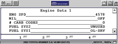
Fuel trims can be used to diagnose exhaust restriction on V-block engines equipped with a catalytic converter on each bank. In many cases, one fuel trim number will be positive, the other negative.
See Photo 6.
But remember that the PCM goes into open-loop mode at wide-open throttle, so fuel trim numbers are no longer being calculated.
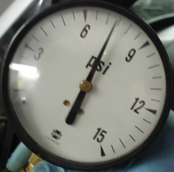
At this point, it became obvious that the Toyota 4-Runner performed well in ordinary driving, but lost power under high rpm, full-throttle operating conditions. Back at the shop, a vacuum gauge test indicated a slightly higher than expected intake manifold vacuum. See Photo 7. At 2,500 rpm, steady throttle, the intake manifold vacuum plummeted to nearly zero.
Suspecting a severe exhaust restriction, we tested exhaust back pressure at idle, 2,500 rpm and snap-throttle, with the highest value being about 4-5 psi. While that number was high, it did not explain the sudden loss of intake manifold vacuum at 2,500 rpm.
 So, at this point, I had to consider incorrect valve timing. Several years ago, we had experienced a 3.4L Toyota that had skipped timing on the passenger-side camshaft due to a seeping water pump that had formed a coolant “icicle” just above the timing belt’s crankshaft sprocket. The icicle fell onto the timing belt, causing the right-hand camshaft to skip timing. That condition was easily diagnosed by recording a 10-psi difference in cranking compression between the right and left cylinder banks.
Removing the upper timing cover on this 3.4L revealed that both camshafts were advanced two teeth on the crank sprocket. In this case, the same coolant icicle had formed and dropped onto the timing belt.
Advanced camshaft timing would explain the relatively smooth idle, good low-speed performance, and the sudden loss of intake manifold vacuum at 2,500 rpm. Keep in mind that engines are much more sensitive to retarded camshaft timing. In practically all cases, retarded camshaft timing results in very low intake vacuum and a pronounced loss of engine performance.
Obviously, air flow was being impeded by the intake valves closing too early. As basic as these test procedures might be, they served to quickly diagnose what had been a very troubling engine performance complaint.