 As Fall rolls around and I have my outside chores done, I’m getting ready to re-wire the electrical system on my old 1955 Chevy 3100-series pickup that my dad bought new when I was 13 years old.
The original system used junction boxes rather than connectors and had only one fuse in the system.
All in all, I doubt if the system contains a dozen wires, two dozen at the most.
Growing up with this truck as I have, we converted to a 12-volt system when we replaced the original six-cylinder engine with a V8 back in 1968.
After installing a 12- to six-volt resistor block to operate the ignition and wiper motor, I ended up with the engine changing speed when I turned on the directions signals.
 Needless to say, 1968 was when I really got my feet wet diagnosing wiring problems.
But, I’ve also kept busy this summer doing part-time mobile diagnostics.
Although most of the local shops have improved their skills, they still run across a few cases that they feel are beyond their diagnostic capabilities.
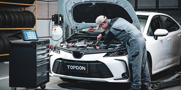
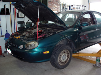
Case in point was a low-mileage 1998 Ford Taurus, which became this month’s Diagnostic Dilemma.
See Photo 1.
During the summer, the speedometer on the Taurus would quit on an intermittent basis.
Of course, when the speedometer would quit, the automatic transmission would default into an intermediate gear and fail to shift into the higher ranges.
 Although a local transmission shop installed a new VSS and performed other repairs as well, the Taurus ran only a few days before the problem resurfaced.
Because the problem seemed to be heat-related, the transmission shop felt that the Taurus’ PCM might be failing.
At wit’s end, the young couple who owned the Taurus visited one of my client shops, who then referred the problem to me.
I don’t like taking in retail work at my home shop, but my client shop felt the problem was beyond its technical capabilities.
The Customer Interview
The customer interview is a vital part of any diagnosis. In short, the couple who owned the Taurus indicated that the problem happened more often on a warm day with the windows rolled up.
The car would have to be driven at least 10 minutes before the failure occurred.
The overdrive light would flash when the speedometer quit working, which is normal on a Ford of this vintage when a transmission-related DTC is stored.
I advised the couple that searching for the problem was akin to finding the needle in the proverbial haystack.
But, with an initial authorization, I proceeded with the diagnosis.
Fortunately, as the case may be, the speedometer and transmission failed immediately after an overnight cold-soak. As soon as the car rolled ahead, I noticed the VSS data stream was indicating zero miles per hour.
Checking the diagnostic trouble codes, I found a P0500 and P1502, stored in the diagnostic memory. These DTCs indicated that the VSS signal had become intermittent. 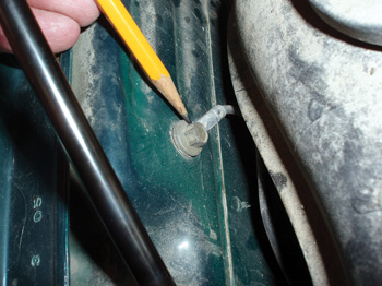
Pending codes also contained a P0500, which indicated that the intermittent condition was becoming a hard failure.
This short test drive completely discredited the customer interview, but that’s often the case because perception is everything to the human mind.
The Diagnostic Strategy
As I mentioned above, several shops turned down the job because they felt it was beyond their technical
capabilities.
But approaching any diagnosis with an open mind and understanding of how a system works are the most vital parts of devising a diagnostic strategy.
In this case, an electronic sensor turns mechanical motion into an electrical signal that switches from positive to negative voltage in a sine wave pattern.
The PCM then converts the frequency of the sine wave into a speedometer reading displayed on the instrument cluster.
How a diagnostic strategy is devised depends upon the configuration of the components and the physical access to each. In this case, the VSS was very inaccessible because it was sandwiched between the engine block and transmission.
 The VSS pigtail lead ran about 8” before it disappeared into a firmly secured engine harness. With the right front wheel removed, I could use one hand to disconnect the VSS wiring, but that was about it.
My first step in devising a diagnostic strategy was to download the wiring schematics, which indicated that the VSS was a two-wire variable reluctor sensor attached to the main engine wiring harness via a two-wire connector.
I also downloaded the power distribution, ground distribution and wiring splice charts as well because they could also be very helpful in locating potential failure points.
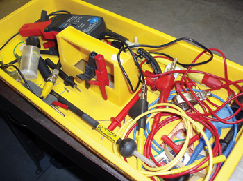
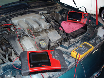
Photo 2 shows my tray full of test accessories.
My first step was to test the disassembled connector and check for correct pin fit with a test pigtail I keep for that purpose.
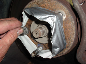
With the pin fit verified, I taped the hub lug bolts as a safety measure to prevent injury when I reached through the wheel well to wiggle-test the wiring with the engine running.
See Photo 3.
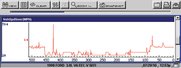
 The simple way to wiggle-test intermittent circuit failures is to graph the voltage on a scan tool that has a voltage or data graphing capability.
See Photo 4.
Because the graph looked pretty ragged, I assumed that the fault was due to a broken wire in the connector pigtail. Because the pigtail and connector had some abrasion damage, I fabricated a new pigtail that attached higher up in the wiring harness. Satisfied that I had found the problem, I reassembled the Taurus for a road test.
Multiple Failures
Fifteen miles and one hot-soak later, the VSS again failed to produce a signal and stored a P0500 DTC. As I explained earlier to the vehicle’s owner, modern vehicles use very light-gauge wiring to reduce bundle size.
I’ve found that many wires can be pulled apart inside their insulation and I’ve also found that a single wire can suffer from multiple breaks. In this case, I knew I had a heat-sensitive failure that was likely to be found further into the engine’s main wiring harness.
See Photo 5.
Going back to the wiring schematic and splice chart, I found that the VSS’s ground wire was spliced together with another sensor ground. Both ground wires eventually terminated at a ground point on the front right-hand inner fender.
See Photo 6.
Because body grounds are exposed to the elements, I instinctively removed the wires, cleaned the connection,
reattached the ground, and sprayed it with some anti-corrosion compound.
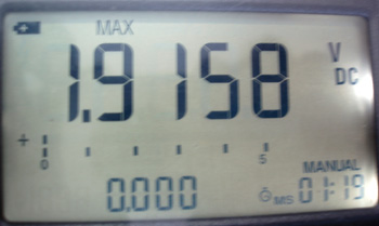
With that done, I disassembled the plastic cover that enclosed the engine harness where it passed over the top front of the engine. After separating the wiring, I attached a digital multimeter to the VSS ground.
I also extended my scan tool around to the engine compartment so I could see when I lost the VSS signal. When I lost the VSS signal, I noticed a rise in the ground voltage.
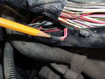
See Photo 7.
Because I knew the wire was supposed to be grounded to the fender, I also knew that if voltage existed in the ground wire, I had an open circuit between the test point and the inner fender ground. Working back through the engine harness, I found the ground splice.
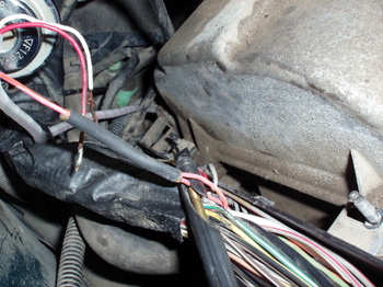
Because I could make or break the connection by wiggle-testing the splice, I knew that the splice itself was the most likely cause of the heat-sensitive, intermittent VSS failure.
See Photo 8.
Wiring Repairs
Repairing wiring harnesses can be difficult because of accessibility problems. Although I try to restore the wiring harness as close to original condition as possible, it can be difficult.
As I mentioned above, I replaced the VSS pigtail by making it longer and attaching it farther into the engine wiring harness because removing the engine harness would have been cost-prohibitive.
See Photo 9.
To create a compact splice replacement, I used 20-gauge wiring, stripped the ends, twisted the bare wire together to eliminate strands, and then tinned the end of each wire with rosin-core solder.
I generally use a small open-flame butane torch or a small butane torch equipped with a soldering iron attachment to fuse the tinned wire ends together. This creates a secure, compact splice without strands that can protrude through taped or heat-shrink insulation.
See Photo 10. 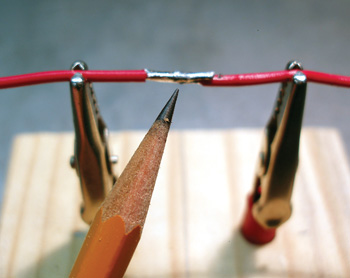
As a final touch, I used two diameters of heat-shrink tube, one on top of the other, to fully insulate each soldered wiring splice.
As you can see, the splice replacement is nearly as compact as the original. With that said, I think that it’s too easy to become overwhelmed by the unknown. I solved the problem by mixing a digital volt-ohm meter, a scan tool and a wiring schematic with a little tenacity. It took time and several attempts before I eliminated both problems, but I finished with a successful repair.
Ohm’s Law
As for re-wiring my old Chevy truck back in 1968, and the engine changing speed with the directional flashers, that was when I learned about Ohm’s Law, which states that, at a constant voltage, increasing the resistance in a circuit (the resistor block) will decrease the amperage of that circuit.
In this case, running the 6-volt directional lights through the resistor block was starving the ignition coil for amperage. Changing the directional signals to 12 volts turned out to be the “quick fix” for the old Chevy’s surging engine problem.