Back in the early 1980s when on-board engine management computers were first introduced, many veteran technicians were taught that all sensor failures could be identified by a trouble code stored in the computer’s diagnostic memory. All that a diagnostic tech should do to solve a driveability problem was retrieve the trouble code and replace the faulty sensor. Thirty years later, most of us realize that no-code sensor failures are a fact of life.
Unfortunately, most no-code sensor failures manifest themselves as intermittent driveability complaints that are difficult to duplicate and even more difficult to solve. So, we continue investing in scan tools, labscopes, and labscope accessories to help diagnose what some techs call a “ghost” problem. In the following text, we’ll take a look at how to utilize one or more scan tool features to detect an intermittent sensor failure.
AN INTERMITTENT STALL
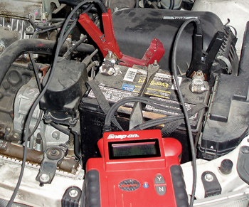
Intermittent stalling complaints are perhaps the most difficult to solve because any component part of the engine’s electronic management system can be at fault, from the PCM itself to a simple ground connection on the engine. The case study I’ll be using to illustrate this topic involves a no-code stalling complaint on a 1997 Toyota Camry. Although this Camry is an older vehicle with about 200,000 miles on the odometer, it well illustrates the basic principles of how to approach a difficult no-code, intermittent stalling complaint. See Photo 1.
During the initial interview, the customer claimed that the stalling condition was becoming worse with time. The vehicle would stall at stoplights and occasionally hesitate at highway speeds. Based upon those symptoms, the owner had replaced the crankshaft position sensor (CKP) with no result.
CODE SET PARAMETERS
Before attempting to solve a no-code failure, let’s look at how the PCM detects failed sensors or sensors that are operating outside of specified parameters. First, the correct operating conditions (enabling criteria) must be present before the PCM can run the test monitor required to detect a sensor failure. In order to “round up the usual suspects” for an intermittent stalling condition, let’s look at some typical enabling criteria for a CKP, O2 and MAF sensor failure.
According to one source, the enabling criteria for a 1997 Toyota CKP “A” circuit failure (P0335) is that, (a) the engine is cranking and (b) the PCM didn’t detect any signals from the CKP or (c) with engine speeds in excess of 600 rpm, it was, at some point, missing the CKP signal during two vehicle trips.
To store a code, the PCM might also apply a numerical standard to a sensor’s performance. Using an oxygen sensor slow response code (P0153) as an example, the response time for the O2 sensor to change from rich to lean must exceed one second of time before the code can be stored. Keeping in mind that the PCM might briefly lean the air/fuel mixture to run this test monitor, the PCM might compare the oxygen sensor voltage against a numerical standard (less than 0.5 volts, more than 0.5 volts), and also numerically compare this response time in seconds with another standard (one second in time).
Another way a PCM might store a code is by “rationalizing” or comparing various sensor inputs. The PCM might measure mass air flow (MAF) sensor performance by comparing the airflow indicated by the MAF with the indicated throttle position (TP) sensor voltage and engine speed. In other words, 75% throttle at 2,500 rpm should mathematically produce an estimated “X” grams per second of airflow. If the MAF’s indicated airflow doesn’t match the estimated airflow, a P0100-series code should be stored. But that isn’t always the case with many applications. The process of rationalization is very application-specific, so you’re going to see differences in how sensor rationalization is applied to various models and model years.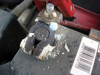
Last, the PCM can detect open, shorted or shorted-to-ground circuits by supplying what is known as a “bias” voltage to the circuit in question. For example, the PCM might supply a 0.48-volt bias voltage to a zirconia oxygen sensor input circuit. Key on, engine running (KOER) with a constant reading of 0.48 volts might indicate an open circuit. A reading in excess of 0.48 might indicate a short to oxygen sensor heater voltage. A reading of 0.00 volts might indicate that the circuit is shorted to ground.
Many PCMs are similarly programmed to measure amperage flow through an oxygen sensor heater. If the current exceeds 2.0 amps or is less than 0.25 amps, a P0135 DTC might be stored, which indicates a problem with the Bank 1, sensor 1 circuit. See Photo 2.
TYPE ‘A’ AND ‘B’ CODES
It’s always important to poll each vehicle module for DTCs because various “B” or “C” body control codes might be present that won’t turn on the MIL. As for engine performance, a type “A” or one-trip failure, such as a severe ignition misfire, will immediately turn the malfunction indicator light (MIL) on and store a P0300-series trouble code. On the other hand, a type “B” two-trip code or pending trouble code won’t turn on the MIL until a second trip confirms a sensor failure.
THE NO-CODE FAILURE
Fortunately, scan tool manufacturers continue to add more diagnostic features, including various TSBs or “troubleshooter” menus for diagnosing vehicle-specific problems. In other cases, on-line professional databases will provide a technician with a list of anecdotal pattern failures and repairs. 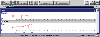
In the case of our Toyota Camry, a professional on-line repair information system indicated that a very high percentage of engine coolant temperature (ECT) sensor failures were causing various types of stalling and hesitation problems. Of course, many of the listed stalling complaints were also caused by a majority of the engine management sensors.
Returning to the scan tool, the most useful feature I’ve found for diagnosing intermittent, no-code failures is the ability of many aftermarket scan tools to graph sensor voltages. After a recent update, my scan tool can graph and record nearly every sensor listed on its menu. Although I use graphing to locate internal wiring breaks and other unusual failures, this was the first time I used it to diagnose an intermittent sensor failure by looking at every data line. In this case, I used the manual trigger to ensure that I would capture any fault.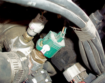
When diagnosing any intermittent problem, it’s important to leave the vehicle in an “as-delivered” condition. Sure, the battery cables might need cleaning, but first check for excessive voltage drop (a maximum of 0.5 volts) from the battery post to the battery terminal. Because I’ve found that many no-code sensor failures can be caused by a bad battery wiping out the keep-alive memory during cranking, it’s very important at this time to check battery state-of-charge (SOC) and condition.
It’s also best to let the vehicle cold-soak overnight and test from a cold start-up the next morning. In the case of my stalling Toyota, about five to eight minutes after a cold start-up, I felt the engine “hiccup” and then recover. I instantly hit the trigger button and captured this display shown in Photo 3.
Reviewing the captured data, I discovered that the indicated ECT abruptly drops from about +140° to -4° F. This failure is self-explanatory because this level of temperature differential will drastically modify the air/fuel ratio in the engine. The apparent reason a P0116 ECT sensor performance code wasn’t stored was because the duration of the ECT calibration failure didn’t meet the enabling criteria for the code. See Photo 4.
In this case, I was lucky to get the capture, because I couldn’t get the failure to duplicate while waiting for delivery of a new ECT sensor. Without the “smoking gun” captured on the scan tool data graph, I could have spent hours, and even days, chasing the elusive stalling complaint that was causing the owner of the 1997 Camry so much grief.