Not that I recommend installing used PCMs, but I occasionally need a rebuildable core to replace a missing or badly damaged powertrain control module (PCM). But lately, I’ve noticed that it’s becoming increasingly difficult to find a used PCM for an older import at a local auto salvage yard. While it’s sheer speculation on my part, this apparent shortage of PCM cores might be caused by too many poorly trained technicians replacing PCMs to solve sensor-based problems. In most of these cases, the problem remains unsolved even as the original and fully functional PCM is casually tossed into the trash when the tech moves on to another job. 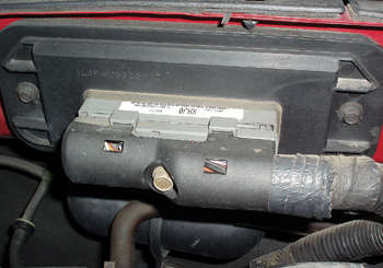
BASIC PCM AND SENSOR WIRING
Understanding PCM wiring circuits is essential to understanding the relationship between a PCM and its sensors. For example, the keep-alive memory in a PCM requires constant battery voltage (B+) to prevent stored diagnostic trouble codes (DTCs) and adaptive data associated with fuel trim values and transmission shift points from being lost.
The PCM also requires key-on voltage to activate the computer’s sensor and actuator circuits. To ensure a complete electrical circuit, most PCMs attach redundant ground wires to the engine block. Practically all PCMs power the various sensors with a 5-volt reference voltage and some might also supply an 8-volt reference to one or more sensors.
WHY PCMS FAIL
While the modern PCM is a very reliable component, water intrusion from a leaking heater core or windshield seal can corrode PCM connectors or short-circuit various internal PCM components. Older PCMs can also develop a temperature-sensitive crack in their circuit boards. In other cases, the PCM can be ruined by an over-voltage condition caused by faulty alternator voltage regulation or over-boosting the battery with a battery charger. Although most modern PCMs have built-in voltage spike protection, voltage spiking caused by something as simple as arc welding on the chassis can degrade or ruin various PCM components. See Photo 1.
In more normal circumstances, PCM actuator drivers are usually the most common failure points in modern PCMs. While some PCMs automatically disable actuator drivers when their amperage draw exceeds a critical level, others don’t have that protection. If, for example, an ignition coil driver were burned out on a PCM, it would be a good preventive maintenance practice to also replace the ignition coil assembly. PCMs with more sophisticated on-board diagnostics can test actuator circuits and store actuator trouble codes in the same manner as with sensors.
BASIC PCM DIAGNOSIS
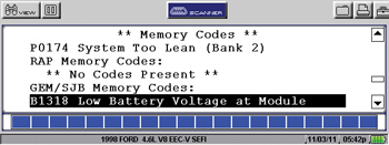
Before diagnosing any PCM or sensor-related problem, it’s absolutely essential to test the battery for an adequate state-of-charge (SOC) and for clean terminal connections. In many cases, erratic cold driveability symptoms and other symptoms related to sensor performance can be traced to low SOC or a bad battery cell. See Photo 2.
The simplest method for testing communications with any OBD II PCM is to connect a “generic” or “global” scan tool or code reader. If the scan tool won’t communicate, check the PCM fuses with a digital voltmeter. If the fuses display battery voltage at both pins, use a wiring schematic to locate and test the PCM’s key-on and B+ terminals for battery voltage. Remember also that high internal resistance in a PCM relay can reduce B+ voltage at the PCM’s key-on terminal, which can cause unusual performance problems and intermittent cranking, no-start complaints that resemble a bad crankshaft position sensor (CKP). To ensure circuit integrity, always clean and tighten the PCM ground connections.
When diagnosing any sensor-related complaint, the PCM ground wires should display less than 0.050 volts in the key-on, engine off or key-on, engine running position. While a few specific vehicle applications might display as much as 0.080 volts, most ground terminals will display close to zero voltage. If voltage is excessive, clean and reinstall the terminals.
In some cases, a sensor shorting to ground may cause a loss of the five- or eight-volt reference voltages. If the vehicle won’t start or the PCM won’t communicate with a scan tool, the most convenient place to begin testing for reference voltage is at the throttle position sensor.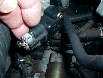
In most throttle sensor configurations, the reference voltage should be five volts and the input to the PCM should be under one volt at closed throttle. If no reference voltage is present, begin disconnecting sensors, including the vehicle speed sensor, to determine which one is shorting the reference voltage to ground. See Photo 3.
SENSOR FAILURES
When the ignition is first turned on, the PCM checks for sensor circuit failures by looking for electrical inputs. If the PCM detects a sensor with an open, grounded or shorted circuit, it usually stores a DTC and illuminates the “check engine” (CE) warning light.
As the engine is cranked, the PCM looks for a signal from the CKP and camshaft (CMP) position sensors. If the PCM doesn’t detect a signal from the CKP, it will not activate the drivers that, in turn, actuate the fuel pump, fuel injection and ignition systems. As the engine starts, the PCM scans the incoming data for increasing engine speed from the CKP and CMP sensors.
Keep in mind that the CKP identifies top-dead-center (TDC) on all cylinders while the CMP identifies the compression stroke on number-one cylinder. If the CMP signal is missing or if the cranking rpm doesn’t immediately increase, some PCMs are programmed to use a default strategy that locates the compression stroke on number-one cylinder by changing the ignition timing 180 degrees. If a default strategy isn’t programmed into the PCM, a missing CMP signal might not allow the engine to start. 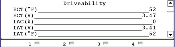
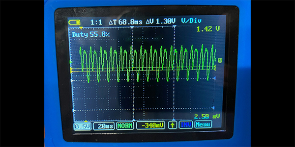
The throttle position, coolant temperature and air flow sensors relay input data to the PCM. The PCM uses that data to calculate actuator outputs like spark advance, fuel injector pulse width and idle speed. Once the engine starts, the PCM looks for changes in engine speed, coolant temperature, throttle position and oxygen sensor activity on your scan tool’s data stream. See Photo 4.
If, for example, the oxygen sensor voltage remains at 0.458 volts, you might be looking at a default rather than a real-time voltage value simply because the oxygen sensor has been left disconnected. If the coolant temperature doesn’t reach the specified value, check the thermostat housing outlet temperature with a non-contact pyrometer. A significant difference between data stream and real-time temperatures might indicate that the coolant temperature sensor is mis-calibrated.
The PCM also scans the incoming data for an increase in airflow through the mass airflow (MAF) sensor. Keep in mind that older imports equipped with mechanical airflow sensors used a minimum airflow value to activate the fuel pump relay. A leaking or missing duct between the MAF sensor and engine can cause a cranking, no-start condition in any engine because the PCM can’t sense the presence of incoming air.
As the vehicle is driven, the PCM processes data inputs from all of the engine’s sensors to adjust actuator outputs like air/fuel mixture ratio, spark advance and idle speed. At that point, the oxygen or air/fuel ratio (AFR) sensors are used to trim air/fuel ratios to the desired values.
THE EFFECTS OF SENSOR FAILURES ON THE PCM
The old “garbage-in, garbage-out” theory of computer operation very well describes the importance of accurate sensor inputs. Sensors usually fail because of circuit problems, calibration errors and data errors.
To illustrate, a circuit failure like a broken ground wire at the throttle position sensor might cause the sensor to indicate a wide-open throttle condition to the PCM, which could result in a false clear-flood mode situation that results in a cranking, no-start complaint. A voltage-biased oxygen sensor might cause a calibration error that drives the air/fuel ratios lean or rich. A data error could be caused by a MAF sensor duct leaking un-metered or “false” air into the engine’s air intake. A data error like this might cause the MAF to under-report the amount of air flowing into the engine, which will cause the engine to run too lean and result in a P0171 DTC to be stored in the PCM’s diagnostic memory.
Sidebar
Oxygen Sensor R&R Tips And Safety Precautions
The oxygen sensor (O2) operates in an extremely hostile environment, where age, contamination and extreme heat can affect oxygen sensor response characteristics. Of the many possible HO2s DTCs, “Slow Response” is the most frequent code developed. Degradation of the signal can be in the form of an extended response time or a shift in the sensor voltage curve. Both conditions reduce the oxygen window, thereby reducing the catalyst capacity for exhaust gas conversion.
Normally, the O2 sensor is supplied with anti-seize compound on the threads so it can be more easily removed at the specified change interval. Over time, the anti-seize compound loses its effectiveness and the sensor can become “welded” into its location, making it nearly impossible to remove using normal tools. Using excessive force to remove the oxygen sensor may damage the sensor and surrounding components.
If the sensor becomes seized in its mounting location, a simple 15-minute replacement job can become a much more complex and difficult task. Replacing the O2 sensor within the specified change interval will minimize the possibility of this problem and additional component damage.
When replacing an oxygen sensor, keep these tips in mind:
1. The primary sensor is on the manifold or the exhaust pipe; late-model vehicles also have sensors farther downstream. Be sure you know which one needs to be replaced.
2. Unplug the wire connection, then spray a penetrating lubricant onto the threaded connection.
3. Use an appropriate oxygen sensor tool.
4. Most oxygen sensors come with a special electrically conductive anti-seize compound applied to the threads, so it’s merely a matter of threading the new sensor into the void left by the old one.
5. Use anti-seize compound to coat the sensor’s threads (some oxygen sensors have the anti-seize compound applied at the factory).
6. Always check the appropriate reference material for the required torque specification. When there’s no torque value given for tightening the new oxygen sensor, treat it much like you would a spark plug. In other words, less is probably better here. Once it’s snug, plug the connector into your car’s factory wiring to finish the task.
Courtesy of Delphi Product & Service Solutions