By Oleg Malin, Vasyl Postolovskyi and Olle Gladso
Contributing Writers and Instructors at Riverland Technical and Community College in Albert Lea, MN
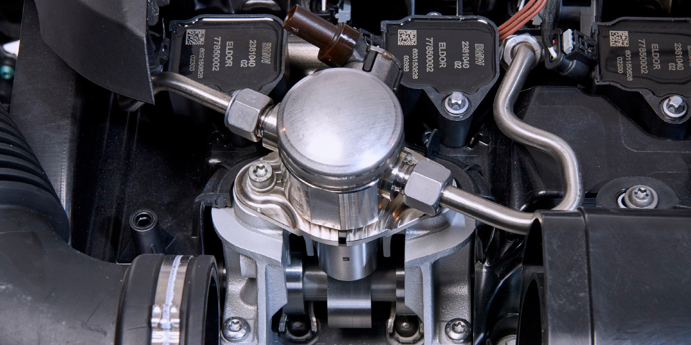
The 2003 Opel Vivaro, equipped with the 1.9 dCi F9Q engine, is one of the first common rail diesel engines from Renault. This is a simple and reliable engine. The problems we are diagnosing on this particular specimen are: hard cold start, blue smoke from the tailpipe, engine shake or miss, increased fuel consumption and decreased power.
The engine on this vehicle was serviced, including a valve adjustment less than 620 miles/1,000 km ago.
A scanner was connected and a very high correction value for cylinder #3 injector: +5 mg/cycle was observed. It looks like the injector is failing, but before condemning it, some more diagnosis is in order.
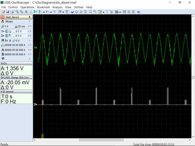
One channel of a USB Autoscope is connected to the crankshaft sensor and another channel is used to connect a current transducer to the fuel injector for cylinder #1.
The waveforms are recorded for use by the CSS script written by Andrew Shulgin (more information about CSS script can be found in March 2012 issue of Underhood Service; in TechShop’s October 2015, and February and June 2016 issues).
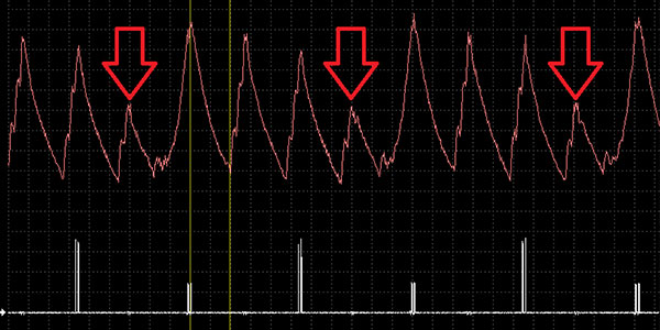
The script is run and the following results are obtained. See Figure 1.
During deceleration, cylinder #3 shows a lower dip (marked with a red circle in Figure 1). This dip indicates a problem with compression. During partial load conditions, the shake or miss is seen (marked with a red rectangle).
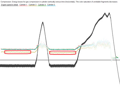
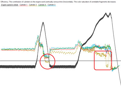
Figure 2 shows what the “Compression” tab uncovers.
It can be seen that the resistance created on the compression stroke by cylinder #3 is much smaller than from the other cylinders.
As verification, the relative compression was checked, as shown in Figure 3, by visualizing the starter current as a graph versus cylinder position. To perform the test, the engine must be inhibited from starting.
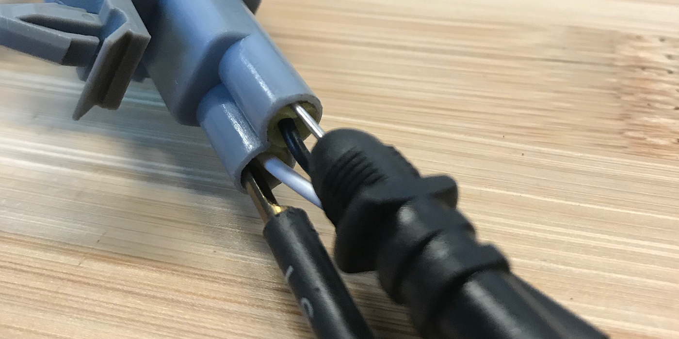
In this case, the connectors from the fuel injectors were disconnected and an injector emulator (a coil from a Bosch common rail injector) was connected to the connector for injector #1. A low amp clamp was attached around one of the leads going to the emulator. This signal was used for synchronization. A high amp clamp, the APPA32 current transducer, was attached to the negative battery cable.
Cylinder #3 shows a distinct reduction of compression. Using relative compression is a much simpler method than attempting to remove the glow plugs, which may not even be accessible and may break during removal attempts.
At this point, we know that the problem is low compression in cylinder #3. All that is left is to determine exactly why this problem exists. Is it the cylinder/piston or the valvetrain?
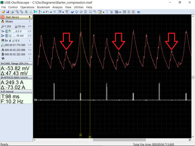
To determine if the problem is cylinder leakage, a piezo transducer was connected through the use of a suitable adapter to the oil filler neck. As shown in Figure 4, this will obtain a waveform of the crankcase pressure pulsations. To synchronize the waveform to the cylinders, a low amp clamp was attached to the wiring for cylinder #1.
The pulsation amplitude variation is minimal. This means that even if there were cylinder leakage, it would be nearly the same for all of the cylinders.
This leaves only two possibilities: a bent piston rod or leaking/misadjusted valves. (It is extremely unlikely that a bad camshaft would cause this amount of compression loss.)
A golden rule is to check the simple things first, so a valve adjustment was performed. The exhaust valve clearance on cylinder #3 was found to be way too small. After proper adjustment, the engine performed as it should.