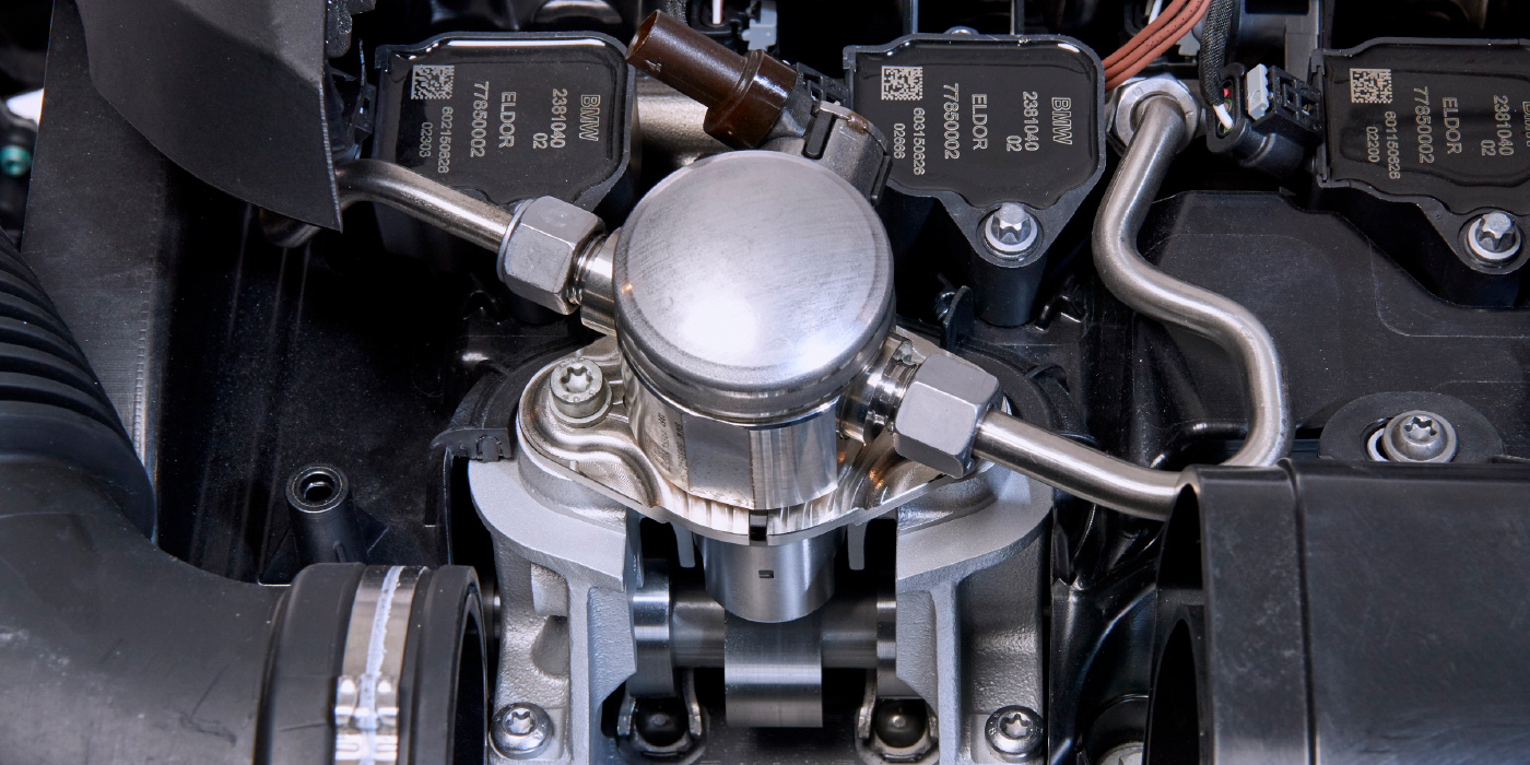
Our subject, a BMW X5, was manufactured in 2004. This vehicle is equipped with the well-known M54V30 engine. The engine is equipped with PFI (Port Fuel Injection), COP (Coil On Plug) ignition and VANOS (Variable cam timing, in German Variable NockenwellenSteuerung).
The stated concern was that the engine was running unusually rough for an inline six, and these engines tend to run very smooth. An error code, DTC P0304 “Cylinder 4 Misfire Detected” was stored in the PCM.
As is often the case, troubleshooting was performed by parts replacement. The first item replaced was the ignition coil for cylinder No. 4. What was the logic, if any, behind doing that?
There is no clear answer. DTC P0304 “Cylinder 4 Misfire Detected” is decoded as “Cylinder 4 Misfire” by many scanners, and the ignition coil or spark plug is the first item replaced. A technician will do well to remember that misfiring means that there is no combustion, instead of “there is no ignition,” and this is an important distinction.
Many technicians are just itching to replace the spark plug or coil when faced with a misfire code. However, if you understand that a misfire code actually means “lack of combustion,” then there are suddenly many possible reasons for the code, such as a defective injector or lack of compression.
In this particular case, the ignition coil and spark plug in cylinder No. 4 were replaced. Since the replacement did not have the desired result, the misfire was still there. The injectors were tested in an injector tester, without a conclusive result. The injector in cylinder No. 4 was replaced, but the replacement failed to give any improvement.
It would have been much easier to simply swap the injector with another cylinder, for example No. 3 and No. 4, much like they could have done with the ignition coil. If the misfire followed the injector, or coil for that matter, then the resolution would be simple: replace the bad part.
However, on the specimen here, an ignition coil, a spark plug and an injector were replaced with no improvement. The “technician” then decided that it was necessary to disassemble the engine to diagnose the problem. Why a compression gauge or a vacuum gauge did not get used is anyone’s guess.
The customer had finally had enough, after having spent a lot of time and money with no result and decided to get a second opinion from another, perhaps more capable, shop.
A famous Russian scientist, Dmitri Mendeleev, coined the following phrase: “Science begins with measuring.” To paraphrase a little: Professional diagnostics begins with recordings and analysis of waveforms. When we see graphics displaying processes as they occur in the engine, we can draw conclusions. Most importantly, the conclusions are completely reasonable.
So, now the vehicle is in our possession. One of the cylinders is obviously not working. That much is visible and audible even without diagnostic equipment. Finding a faulty cylinder is one of the simplest tasks for a diagnostician. Engine shake means, in essence, that the engine is out of balance, most likely due to uneven power contributions from the cylinders. The task then is to find the reason for the difference. Basically, there can only be one or more of the following three reasons: the mechanical part, the ignition system or the injector.
Where to begin? The best way for consistent diagnosis is to compare good cylinders to bad cylinders. Since the engine is equipped with an ignition system with individual coils that are controlled by the PCM, it is relatively easy to compare primary waveforms between cylinders. Does it make sense to do that? Yes. In this case, we used the engine analyzer USB Autoscope IV by comparing primary voltage in good and faulty cylinders.
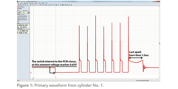
Figure 1 shows the waveform of the primary voltage from the coil in cylinder No. 1, where there are no discernible problems. Note that this is a “multispark” or “multistrike” ignition system. BMW engineering. There are seven sparks visible in the waveform.
After analyzing the waveform, several conclusions can be drawn:
• Supply voltage on the coil is 13.95 V.
• It is unlikely that there are any problems with the supply voltage of the ignition coils or the charging system.
• Coil on time (“dwell”) is 2.5 ms.
• All seven sparks take place.
• Burn time of the last spark is 1.5 ms.
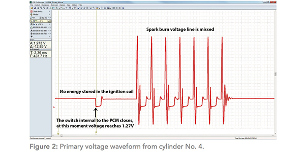
Pay attention to an important nuance. The very beginning of the process of energy accumulation in the coil is the moment when the switching element (transistor) is switched on in the PCM. The voltage shown at this moment is the voltage drop across the electronic switch that controls the primary circuit. On the primary voltage waveform in a good cylinder, it is 0.65 V. This is a normal value, approximately the same is observed on most known-good ignition systems. Figure 2 is the primary voltage waveform from cylinder No. 4, where the misfire is evident.
Let’s continue our reasoning. What conclusions can be made by looking at this waveform? To begin with, it is obviously abnormal. Why did the previous technician decide that spark occurred? They may have checked it visually by removing the coil and inserting a spark plug into it. Visually, the spark will be observed, because the breakdown of the air gap on the waveform clearly takes place. However, there is no spark line. The actual spark duration that ignites the mixture is completely absent.
Remember that in order to ignite the air-fuel mixture, a certain amount of energy must be applied to it. If the supplied energy is lower than needed to guarantee ignition of the mixture, ignition may not occur. Therefore, the spark should not just arise, but also burn for a period of time. Look at it this way; the mixture is not ignited by the breakdown of voltage across the spark gap, but by the spark duration. If the spark duration is too short or non-existent, then the mixture may not ignite. The duration of the high-voltage breakdown is too short.
Normal consensus is that spark duration or burn time required for consistent ignition should be at least 0.8 – 1.0 ms. The higher the value of the spark burning time, the higher probability of successful ignition, especially in transient and high-load modes. That is why high-level manufacturers, such as BMW, use multispark ignition. In our case, this is a pack of seven sparks following each other.
The reason for the misfire is found; now for the repair. Look at the voltage at the time of the start of the energy storage process in the coil. The voltage is 1.27 V and we remember that it should be about 0.6V.
The voltage drop across the electronic switch is high. The waveform also clearly shows the primary current limiting circuit in operation. The accumulation of energy in the coil is almost absent. Where is the problem? Since all ignition system factors are controlled by the PCM, that is where the problem must be.
On this vehicle, the PCM is located in an enclosure located between the engine panel and the passenger compartment.
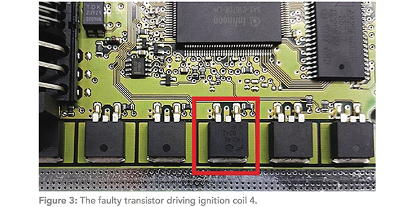
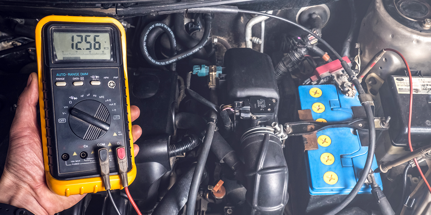
We opened the enclosure, removed the PCM, disassembled it and looked at the printed circuit board. It was easy to see that there were six identical transistors that are uniquely identified as control switches for the ignition coils. A simple and effective test is to use a comparison method. In this case we used a DMM to measure and compare the resistance between the leads of each transistor. Five of the six transistors had resistance of about 27-28MΩ but one showed 3MΩ. The real reason for the misfire is finally found. Figure 3 on page 11 shows the faulty transistor.
Next task was to find a suitable transistor and use it to repair the PCM. Most all PCMs of this vintage use a similar transistor and most of these are interchangeable.
Any of the following transistors can be used:
• Infineon BTS2140-1B
• Infineon IRGS14C40L
• Fairchild ISL9V3040S3S
• STM STGB10NB37LZ
• ON Semiconductor NGB8202NT4
• Intersil HGT1S14N36G3VLS
The first transistor of this list, BTS2140-1B was in stock at the shop. The faulty transistor was replaced and the PCM was reassembled and reinstalled. Upon retest, the misfire was gone and the primary waveform from cylinder No. 4 was identical to the other cylinders.
Conclusion
All we did was perform some basic testing to find the problem. Note that some technicians may be uncomfortable with taking PCMs apart to pinpoint and, maybe especially, repair problems. That is understandable, but with increasing levels of electronics on vehicles, board level diagnostics is a valuable skill to have. With that said, checking ignition systems by picking up the waveform of the primary circuit voltages and comparing them to another is one of the basic skills in engine diagnostics that technicians need to have to be successful.
In this case, my tool, the USB Autoscope IV made the diagnosis very simple. The primary voltage waveform reflects most all defects that occur in the ignition system, and the ability to analyze this waveform is a valuable basic technician skill.
These types of problems are particularly easy to diagnose because the comparison method works great here. We simply compare and perhaps record waveforms from a good as well as the bad cylinder. Matching them will usually lead to a rapid and accurate diagnosis. It doesn’t even matter to us whether the shape of the waveform looks right, what is important for us is that it is the same (or, on the contrary, different) in different cylinders.