By Olle Gladso, Vladimir Postolovskyi and Andrew Bezhanov
Contributing Writers and Instructors at Riverland Technical and Community College in Albert Lea, MN
The first installment of Unconventional Diagnostic Methods can be found at http://bit.ly/16zhyTw. Here we delve further into features and functions of DMMs.
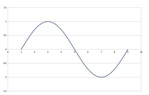
Almost all multimeters can measure “alternating” (AC) and “direct” (DC) voltages. However, many multimeters can’t correctly display DC voltage in the AC mode because of the simplified measurement circuit. Most all DMMs can’t display AC voltage properly while in the DC mode either. Additionally, if the waveform being measured is not a true sine wave, the meter will often display wrong values. Figure 1 is an example of a sine wave, while Figure 2 is an example of a more complex waveform. Most DMMs would correctly read the average value of the waveform in Figure 1 as 0.707V.
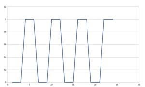
To avoid read errors when measuring signals that are not true DC or true sine waves, choose a DMM that says it is a true RMS meter. Non-true RMS meters “assume” that all AC signals are sine waves.
A DMM with the proper specifications can also stop you from diagnostic mistakes. Figure 3 shows how a meter set to the AC scale gives a voltage value double of what it actually is. Since the battery produces no AC voltage, the correct read-out should be 0V as shown on the DMM on the left.
Even though there are very few signals present in a vehicle that are true AC, the measurement mode is useful in other circumstances as well. A DMM in the AC measurement mode will also show pulsating or on/off DC voltages. On/off voltages are very common in modern vehicles. 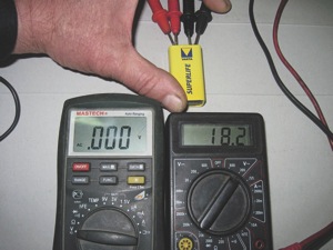
A DMM of the proper type can be used to discern between a continuous and an on/off DC voltage. If it is an on/off signal, the AC measurement mode will show some value. For example, a 5V signal that is “on” half the time and “off” half the time will show 2.5V in both the DC and the AC measurement modes. If the meter reads something other than 2.5V, the meter cannot properly read the voltage (not a true RMS meter), or the ratio of “on” time to “off” time is something other than 1. It should be mentioned that the ratio is usually expressed as the ratio of “on” time to the total cycle time and the ratio is called duty cycle. A signal with half the time “on” and half the time “off” is said to have a 50% duty cycle. Some meters can read the duty cycle directly.
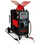
DMMs can also measure AC and DC current in addition to AC and DC voltages. Generally, no extra equipment is necessary to measure current; perhaps, except for the meter fuses if you blow them. Most meters are limited to 15-20A maximum current before the fuse will blow. The fuses tend to be expensive compared to normal automotive fuses. You may be tempted to replace them with inexpensive fuses, but don’t do that. The proper fuses are designed to break the circuit even if high voltage and current is present. The cheaper fuses may allow an arc to be sustained and cause damage or death. One potentially major problem with using a DMM to measure current is that the circuit must be opened up to connect the meter.
For higher current measurements and for using an oscilloscope to measure current, a current probe will be necessary. Unfortunately, these can be quite expensive. Why use an oscilloscope? In order to create a diagnostic method, you must first learn the operating principles of the system or circuit. An oscilloscope is ideally suited for this purpose, because it allows you to “look inside” the circuit. Once the circuit and its operating principles are understood, it is possible to simplify the procedure and to use simpler and cheaper devices for diagnosis “in the field.” A DMM will often not be as accurate as an oscilloscope, but the result is usually good enough to determine if the circuit is operating as intended or not.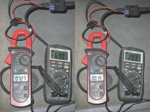
As stated earlier, current can be measured by a DMM directly. Since we need to open the circuit to insert the meter, it is sometimes necessary to cut a wire. This should be avoided at all costs, since it compromises the integrity of the wiring harness and can make it difficult to find problems in the future.
The easiest access to measure current is at the fuse. To do this, use a fuse adapter and connect the DMM to the adapter. There should be a fuse in the adapter to prevent damage to the vehicle’s wiring or the meter itself.
Using a fuse adapter usually makes it easy to measure current from, for example, the fuel pump. Is there a purpose in measuring fuel pump current? The fuel pressure and/or a restricted fuel filter can’t be accurately determined based on current consumption because different fuel pumps have different power requirements. Even if the current consumption data is inaccurate, it can still be useful for giving an initial direction in the troubleshooting process. Now, we are going to go one step further and compare the different values obtained when measuring “direct” vs. “alternating” currents.
Most fuel pumps have a commutator-type motor, which has brushes that will intermittently lose contact with the armature as the brushes move from one commutator bar to the next. We can’t readily look inside the motor to determine the degree of wear of those brushes. Worn-out brushes are often diagnosed as a failure of the pump’s mechanical parts, such as the impeller. The actual failure is technically unimportant since the fuel pump will need to be replaced in either case.
Since there is intermittent brush contact with the armature, current consumed by the fuel pump motor will be in the form of an uneven or pulsating (on/off) DC current. As the brushes and/or the commutator wear out, the contact will gradually get worse, with more and more uneven current. As the amount of ripple (or on/off) current increases, the steady or DC current part of the total current will decrease. A fuel pump consumes a certain amount of power to pressurize the fuel. Where the brushes don’t make contact, the motor will slow down, and where contact is re-established, the motor will speed up.
This increases wear and tear on the commutator segments that do make contact, causing ever larger areas of poor contact. Eventually the flow and/or pressure of the fuel pump will be affected — it will increase, reducing the flow rate and pressure of the fuel pump.
If the fuel pump stops on a commutator segment that doesn’t make electrical contact, the pump will not restart. This occasionally happens when a vehicle with a worn fuel pump is shut off. The vehicle won’t restart. A common “test” is to knock or bang on the fuel tank while attempting to start the vehicle. The vibration may move the brushes or the commutator just enough to re-establish electrical contact. If the vehicle restarts, it’s assumed that the problem is the fuel pump, which it often, but not always, is. 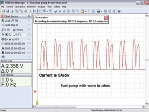
A very common situation that many have experienced is when a no-start vehicle is towed in. Upon initial diagnosis, the vehicle starts and runs with no problem detected. This scenario may or may not be connected to the fuel pump since the vibration from being towed in may have affected any number of electrical connectors, modules or relays. One simple method that can be used to verify is as follows: Use a fuse adapter and insert in the fuse box instead of the fuel pump fuse. Connect your DMM set to the 10A scale or your current probe to the adapter and start the engine. Measure both the AC and the DC component. See Figure 4.
If the AC current value is approximately 10% of the DC value or less, then the brushes and/or the commutator in the fuel pump is in good condition. If the AC current is approximately 50% of the DC current or more, the fuel pump needs to be replaced.
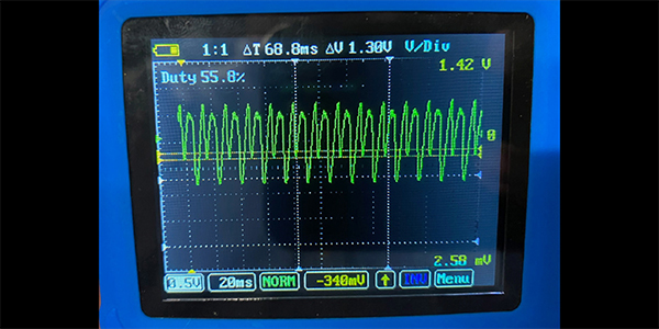
Figure 5 is an oscilloscope waveform taken from a fuel pump with severely worn brushes. Notice that the DC and AC component as shown on a current clamp is almost equal at 2.3 and 2.5A, respectively.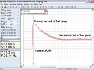
A good fuel pump will have a fairly substantial “inrush” current on initial start up. This is because a stalled armature basically represents an electrical short. As the armature starts to move, electrical current is induced into the windings. This is because the windings move in a magnetic field. The induced current is in the opposite direction of the applied current and will counteract or “fight” the incoming current. The counteraction causes the current consumption to go down to a value that depends on the load applied to the pump motor. The load is heat, friction and the actual work the motor is doing. The “humps” are caused by the commutation where the brushes move from one bar to the next. See Figure 6.
If the fuel pump is experiencing high friction from, for example, worn-out bearings, the steady 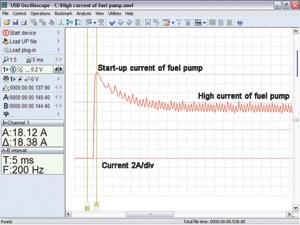 state (where the motor has settled down) will be higher than normal. The actual specification will vary some, depending on the fuel pump type and the normal system pressure. Higher system pressures will cause higher current draw. See Figure 7. It’s advisable to test several good fuel pumps to get a feel for what normal values are.
The final installment of “Unconventional Diagnostic Methods” will be featured in the December issue of TechShop.