By Olle Gladso, Vladimir Postolovskyi, Andrew Bezhanov
In the previous installment of Unconventional Diagnostic Methods (http://bit.ly/17UbxYX), we continued our discussion of unconventional uses of a digital multimeter (DMM). This article concludes our series.
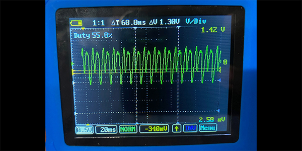
Severely worn brushes and/or commutators can show as intermittent glitches in the waveform. See Figure 1. Note that fuel pumps can be equipped with an axial or a radial commutator. The radial commutator design tends to show a “dirtier” waveform. 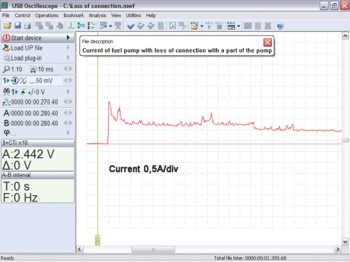
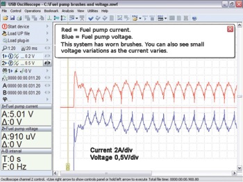
The waveform in Figure 2 shows loss of mechanical connection between the electrical motor and the impeller. If the intake strainer (sometimes called a sock) is plugged, the fuel pump impeller may start to cavitate where the fuel is literally evaporating at the impeller. The low pressure caused by the plugged intake is adding to the low pressure behind the impeller vanes, causing the fuel to “boil.” See Figure 3.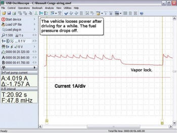
The fuel pump may stall or have stalled. This could be caused by debris in the fuel tank such as rust particles, or a failure of the pump itself, such as the impeller breaking apart. A current waveform will clearly show this issue (Figure 4). The steady-state current consumption of a stalled pump will be very similar to that seen as inrush current when an operational fuel pump 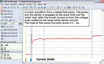 starts up. The current will be two to three times that of normal running current.
The current ramping technique can be used to check just about all electric motors that utilize commutators and brushes. Stepper motors operate differently, with different waveforms associated with them, but that is outside the scope of this article.
Many of the electric motors encountered in automobiles may have current draws in excess of what the built-in ammeter in a common DMM can handle. The limit is typically 10A, with some 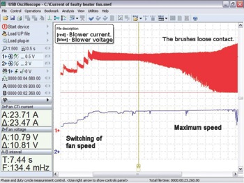 capable of handling 15 to 20A. Figure 5a shows a blower motor that is consuming 23A, well in excess of what a normal DMM can handle. Note the pattern that shows bad brush contact. This blower may run poorly at high speed, may run well for a while and then fail, or it may intermittently fail to operate at all. An electric motor with this type of problem may additionally cause blown fuses and failed wiring and/or switches. This is due to repeated inrush current as the motor speed falls off and regains. See Figure 5b, which shows the current after the blower is
 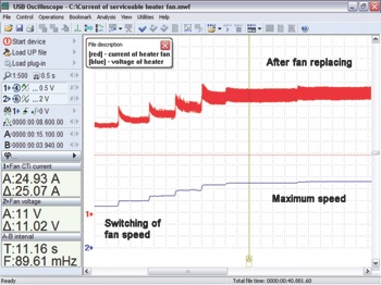 replaced.
One way to get around the current limitation of a typical DMM is to use a current (amp) clamp/probe/ transducer. These tend to be fairly expensive, but the benefit of not having to open the circuit to insert an ammeter in series and not blowing fuses if misconnecting is definitely worth something!
The amp clamps use a sensitive Hall effect device. (A semiconductor that is sensitive to magnetic fields.) The sensors are very sensitive and can be affected by the earth’s magnetic field, temperature, as well as magnetic fields surrounding nearby wires, relays and motors. Because they are so sensitive and easily affected, they need to be calibrated or zeroed before use. This is usually accomplished by pressing a button or turning a dial until the display reads close to zero. The calibration should be done with the probe held close to where it is to be used and oriented in the same direction as its intended use.
Amp clamps can be equipped with a display, or with output jacks. If the probe is equipped with output jacks, the output is usually standardized to, for example, 1 mV per A. This is usually shown as 1mV/A. Other values such as 10mV/A or even 100mV/A can be seen as well. As a general rule, a more sensitive probe will have a larger mV/A value.
Although most amp clamps have zero voltage output for no current flow through the wire they 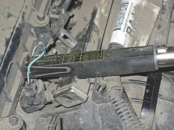 are clamped to, and must be zeroed before use, there are some exceptions. The amp clamp shown in Figure 6 has an output voltage of 2.5V when there is no current flow through the measuring wire. If the direction of current flow is in the positive direction, the output voltage will be higher and, consequently, if the current flow is in the opposite direction, the voltage will be lower. This can be beneficial when using an oscilloscope. We can set zero, at 2.5V in the center of the screen. Higher voltages mean positive current and lower voltages mean negative current. This particular probe has no zero adjustment and is primarily meant for oscilloscope usage. It can be used with a DMM, but some calculations will be necessary to arrive at the correct current values. This particular probe has 500mV/A or 100mV/A as settings — an output voltage of 2.6V would mean one A of positive current flow and 2.4V would mean one A in the opposite direction.
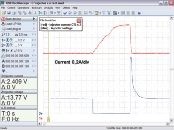
As can be seen in Figure 7, this particular probe has very good resolution and the pintle opening “hump” can be clearly seen. Note that on the voltage waveform we can easily see the pintle closing as well.
Conclusion
By thinking “outside the box” and using our tools to their fullest potential, we can diagnose more of the perplexing problems without spending an undue amount of time on them. In particular, the technique where you use your diode test function to check wiring integrity back to the PCM can be a real time saver. I have tried the technique on a number of different vehicles and it works.
The first installment of Unconventional Diagnostic Methods can be found at http://bit.ly/16zhyTw.