This article will address a misfire code from a different vantage point. It will look at a plan of attack for when a code is being set intermittently. The code we are referencing is P0302-Cylinder No. 2 Misfire Activity Detected.
While I’m very aware that this code has been encountered by many, this failure was unique in that it allowed one to witness theory truly come to life. The owner of our subject vehicle, a 1999 Volkswagen Passat, states it does not misfire all the time, but only once the vehicle reaches normal operating temperature. After the vehicle runs for quite some time, the misfire activity begins.
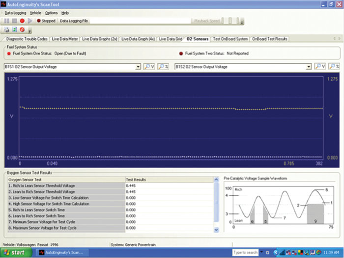
The first step in our analysis is to verify the customer’s complaint. We verified the concern and the pre-oxygen sensor went low at the point of misfire activity. When the misfire activity began in cylinder 2, there was unburned fuel as well as oxygen in that cylinder. The oxygen sensor went low in reference to the additional oxygen that was present in the cylinder, and reported that information to the PCM that the system, at that moment, was running lean. After the misfire activity was evident, the system went into what is called “open loop fault.” The oxygen sensors went flatline (see Figure 1) and there appeared to be no corrective action taking place.
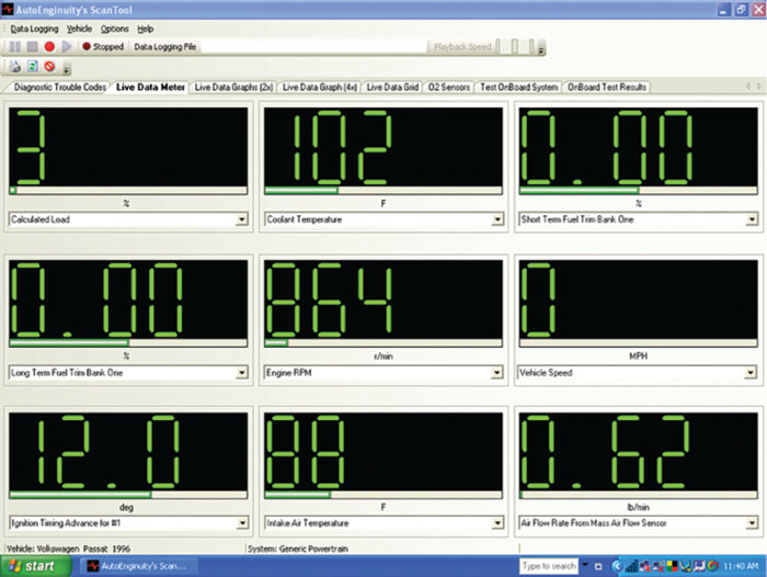
A review of short-term and long-term fuel trims revealed values noted at zero (see Figure 2). (The data is being obtained using an AutoEnginuity scan tool.)
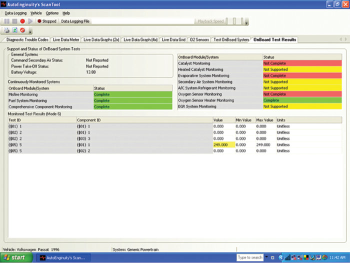
I then also reviewed mode 6 data; it showed that all monitors have run and passed except the oxygen sensor, catalyst and EVAP monitors (see Figure 3). The misfire activity is now present and consistent. It is interesting to note at this time that misfire activity will prevent monitors from running as designed. The enable criteria must be met in every case. In my opinion, mode 6 data should be reviewed each time a vehicle is scanned.
I then decided to try my misfire software (ACE Detective) to see if it would offer some additional information for review. The software works by looking at exhaust pulses to determine what cylinder(s) may be the guilty party. It also looks at data that is input by the user to make an attempt to determine if the misfire may be ignition or fuel related.
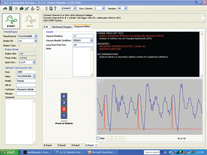
The assumption is, per this observer, that it has already been verified that engine mechanical is sound. We then provide data from our testing; the vacuum gauge showed a vacuum level of 17” Hg and the needle gauge was steady. A long-term fuel reading of zero was documented. (See Figure 4.) The software then provided the following diagnosis:
Diagnosis: Persistent misfires detected per cylinder No. 2
Ignition Suspected
Recommendations: Analyze primary or secondary ignition system
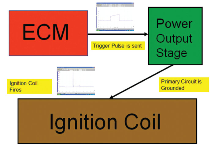
It was now time to scope the ignition system, but a good understanding of how this ignition system works is needed. I decided to do a block diagram analysis of the ignition system to provide an overall understanding. The following diagram (Figure 5) provides a step-by-step process of how this system works.
Step 1: The ECM sends a trigger pulse to the power output stage module, the power output stage acts as an ignition module.
Step 2: Once the trigger pulse is received by the power output stage module, the power output stage module will then ground the primary circuit.
Step 3: Once the primary circuit is grounded and the dwell period ends, the ignition coil will fire the spark plugs.
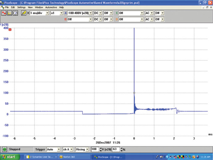
A scope pattern of the primary ignition for cylinder No. 1 and 2 is shown in Figures 6 and 7.
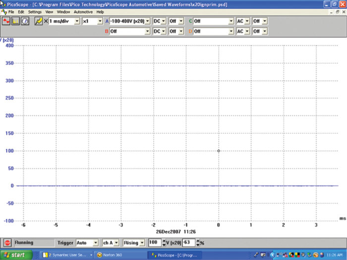
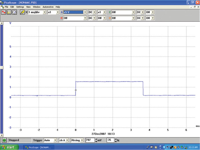
The previous two patterns show that cylinder No. 2 appears to have an ignition issue. We’ll start our analysis by using the block diagram we created. We will first check to see if the PCM is sending a proper trigger pulse to the output stage module. Figure 8 shows what the pulse looks like with no load being placed on it. The connector to the output stage is disconnected.
The PCM is sending a trigger pulse to the output stage module, when the connector is placed back on the output stage module, the trigger pulse will be checked again. This time the pulse will be viewed under a loaded condition (Figure 9).
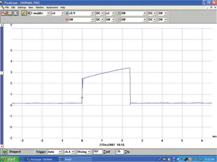
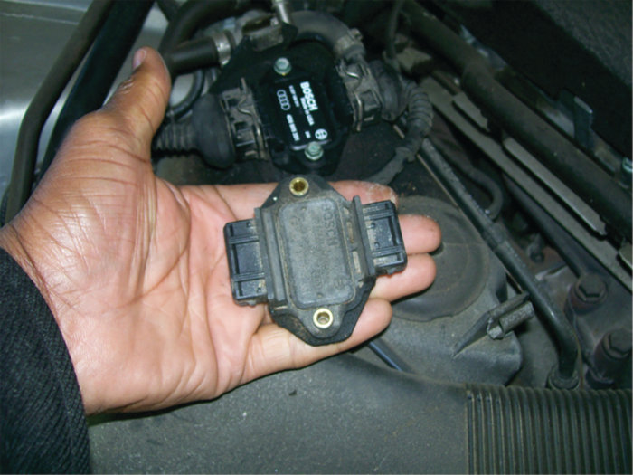
All four cylinders were checked under the loaded condition. All patterns except cylinder No. 2 showed the correct loaded pattern. The output stage module was determined to be at fault. See Figure 10.
This Pulling Codes case is now solved.