 At the typical repair shop, six-year-old vehicles (and there are 184 million of them on the road today) are some of the most common vehicles driving into the bays.
And, since these vehicles are out of warranty, they will fuel service opportunities for the aftermarket and require more attention from independent repair shops like yours.
In particular, one growing service area is diagnostics, especially as it relates to the expanding electronic content in today’s vehicles.
As vehicle makers add more electronic gadgets and emissions/safety requirements become more stringent, the OEMs quickly realized with current wiring harness and sensor layout methods, it would become nearly impossible to manage and manufacture the next generation of vehicles.
 Vehicle “data bus” units helped to solve this dilemma by eliminating additional wiring and the need for multiple sensors.
In the auto repair world, the term used to describe the design, layout and behavior of a serial data bus configuration is “topology.”
Modern vehicles typically have more than one serial data network and even more modules than before, which all must obey and conform to the topology the engineers have specified. And two-wire buses have a topology that dictates they are wired electrically in parallel.
A module on a serial data bus is called a “node.” A scan tool also becomes a node on that bus. And even some sensors and switches can be nodes.
The network starts in pins six and 14 of the Data Link Connector (DLC). The CAN bus lines pass through several modules including the PCM, BCM and fuel pump module. The CAN bus lines exit the node for the 4WD system and terminate in a 120-ohm resistor.
Reading the Wiring Diagram
As a technician in the modern vehicle era, you’re going to need to understand these “bus lines.” The dotted line at the edge of the component, node or module indicates where the CAN bus enters and exits.
 Some schematics may include other information in the boxes with two arrows pointing in opposite directions.
All two-wire CAN bus lines terminate in a resistor(s) of a known value. This is what produces the correct amount of voltage drop.
Bus Configurations
There are three types of bus configurations that you will come in contact with — loop, star and a hybrid of both.
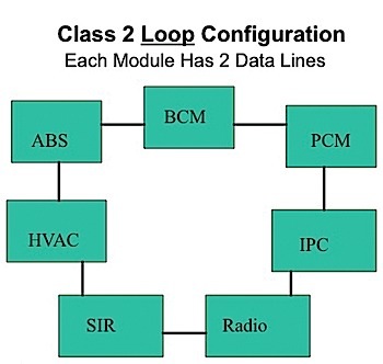
In a loop system, the topology of the nodes or modules is connected electrically in parallel.
Each node has two wires that connect it to the bus. This system multiplexes the nodes together so information can be shared along one circuit. With this system, all of the nodes can turn on a check engine light in the instrument cluster through the use of information within the circuit.
Each of these modules can communicate something to another module. For example, the HVAC would want to communicate with the BCM to ask permission of the PCM to turn on the compressor clutch by energizing the relay.
If you had an open circuit between the BCM and PCM, the PCM could still communicate to the BCM, although it would have to go through the other modules. Communication still takes place if you have one open circuit.
But, if you had two open circuits between the BCM and PCM, and an open circuit between the IPC and Radio modules, the PCM would be isolated and would not be able to talk to the BCM or the ABS module.
 Shorts in a Loop
The problem with a loop during diagnostics is if a short circuit occurs. The loop configuration can be easy to diagnose because, even with two open circuits, nodes are isolated off the bus. But in a short circuit, with the modules in parallel, the whole circuit goes down.
When a bus shorts, it can be a difficult process to isolate the offending module or section of wiring. In case a module itself shorts out the bus, you would literally have to unplug them one at a time to see which module eliminates the short circuit. That would not be a good scenario in the repair world because it would take up a lot of time to gain access to those modules.
Shorts are one disadvantage of the loop configuration. The advantage is, however, you have redundancy of wires. Therefore, we’re more impervious to an open circuit issue.
Star Bus Configuration
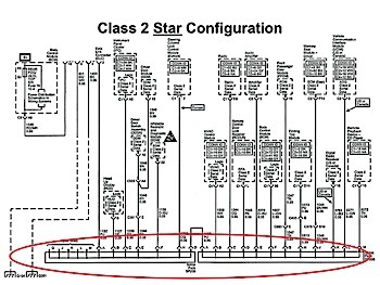
The star configuration’s topology uses a comb, butt connector or shorting bar. It plugs into a female connector.
All of the modules have a single wire coming out of them on the serial data bus to that one common connector that would tie them all together in parallel.
See Figure 1 above.
The star configuration got its name from the computer industry. For example, an Ethernet connection is a star configuration with computers, printers and servers all connected to an Ethernet hub.
Star connectors are often located near the DLC, but note there are exceptions. And, some manufacturers solder them in place, while others don’t, allowing for the connector to be removed a lot easier. On some vehicles, the star connector can be removed and a meter can be connected to each circuit to test for shorts to power or shorts to ground.
Being able to recognize whether the topology is a loop, star or hybrid configuration will make testing and diagnosing shorts, grounds and communication errors faster and more effective than steps and flow charts.
Knowing how both shorts to opens and normal shorts (power and ground) behave on a loop or star can help you formulate a more effective plan of action so you can do more in less time.
Loop/Star Hybrid Versions
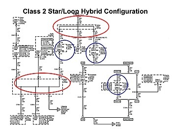
Automakers may also combine both loop and star topologies in a single-bus system.
They may wire them in a combination of both the star and the loop configuration. Both systems have a number of nodes on them that talk on the loop and star.
See Figure 2 above.
 If you know the theory on how this type of bus works and there is a short to ground or power, the next step is to remove the splice packs and check the nodes.
If the short goes away, the next step is to unplug modules one at a time to see if that short comes back.
If the short is still present with the splice packs removed, it could be the nodes in the loop configuration. In this case, the ABS and instrument cluster modules might be a source of the short to ground or power and are connected to the splice pack.
To eliminate them as problems, you’ll need to unplug and check these modules one by one.
Kicking the CAN
This article is adapted from Automotive Video Inc.’s “F.R.E.D. Kicks the CAN” video series. This video will show you how you can use your voltmeter, ohmmeter, lab scope and scan tool to diagnose network problems on the vehicles in your shop. Both the latest CAN buses, as well as earlier networks, are explained in an easy-to-follow video format that shows you exactly how to get to a diagnostic decision quick with the latest real world training.
For more information, visit www.auto-video.com.