Since the oxygen sensor is in the exhaust stream, it can become contaminated over time. Much like a spark plug, the oxygen sensor can be examined and “read” to determine what the cause of contamination might be.
• Black sooty deposits would indicate an excessively rich fuel mixture condition or oil blow-by in an older engine.
• A common type of contamination is due to coolant being burnt in the combustion chamber likely due to an engine gasket leak. See Fig. 3. 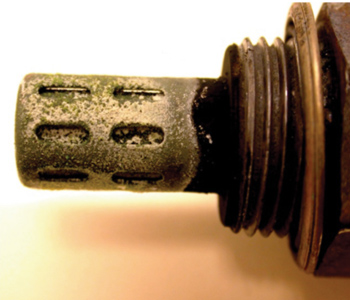
• Lead poisoning is no longer common, due to the lack of leaded fuel, but the emulsifying of the “terne” plating inside a steel fuel tank due to the excessive use of fuel system cleaners or alcohol can cause this same condition.
Typical Switching Oxygen Sensor Diagnosis
• Look at the sensor voltage when the engine is cold and the ignition is first switched on. The heaters will cause the sensor to conduct current. Watch for the bias voltage to gradually lower as the sensor heats.
• Watch for the sensor to come down to less than 100 mV within three minutes of KOEO time. After three minutes, all sensors should have about the same voltage with the KOEO. A failed or contaminated sensor may be slow or may not get down to 100 mV at all.
• If one of the sensor voltages remains high, that sensor could be causing a no DTC driveability concern.
Oxygen Sensor Replacement
• The primary sensor is on the manifold or the exhaust pipe; late-model vehicles also have sensors farther downstream. Because many late-model vehicles have multiple oxygen sensors, be sure you correctly identify the bad sensor so you do not mistakenly replace the wrong one.
Vehicle manufacturers identify “bank1” vs. “bank2” and “front/rear” vs. “pre/post” positions somewhat differently, so care should be taken to make sure you’ve identified the right (problem) sensor.
• Unplug the wire connection, then spray penetrating lubricant onto the threaded connection.
• Use an appropriate oxygen sensor removal tool.
• Most oxygen sensors come with a special electrically conductive anti-seize compound applied to the threads, so it’s merely a matter of threading the new sensor into the void left by the old one.
• If the new sensor does not have anti-seize pre-applied, be sure to apply some to the threads prior to installing the sensor. Do not put excessive amounts of anti-seize onto the threads. Getting anti-seize compound on the sensing area will contaminate it.
• Always check the appropriate reference material for the required torque specification. Once it’s snug, plug the connector into the vehicle’s factory wiring to finish the task.
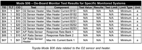
• Using Mode $06 Test Data
– Once an oxygen sensor repair is made, Mode $06 data can be useful to determine if the oxygen sensor is operating correctly and the repair was effective.
– Mode $06 is the actual system test data that OBD II looks at when it decides to set a pending or current fault code.
• The chart below is an example of the Mode $06 data that can be obtained with regard to the oxygen sensors.
Courtesy of Delphi Product and Service Solutions.