This bulletin describes the valve timing procedures necessary when installing a timing belt or transfer drive chain on 1996 Elantra models. The importance of this information cannot be over-emphasized, because improper valve timing can result in driveability problems, such as loss of power, poor idle quality and, in severe cases, stalling and cylinder head damage.
Timing Belt and Drive Chain Installation:
Caution: If the cylinder head was removed, the camshafts and crankshaft must be set to TDC before installing the head.
If camshaft(s) removal was necessary, follow steps 1-5. If camshafts were not removed, proceed to step 6.
1. Install the transfer drive chain onto the transfer gears. See Fig. 1. Note: Align the timing marks to the bronze-colored or punch-marked links on the chain.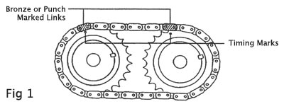
2. Apply assembly lube and install the camshafts.
3. Install bearing caps, checking the marks on the bearing caps for proper location. See Fig. 2. Tightening Torque: 12-14 Nm (9-10 lb.-ft.).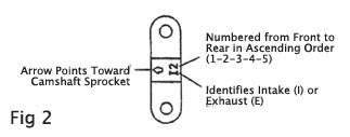
4. Using a special service tool, p/n 09221-21000, install the camshaft oil seal. Note: Prior to installation, apply a light coat of motor oil to the internal and external surfaces of the seal.
5. Install the camshaft sprocket. Tightening Torque: 80-100 Nm (59-74 lb.-ft.)
6. Align the mark on the crankshaft sprocket to the protrusion on the front case.
7. Align the camshaft sprocket so that the hole in the sprocket web is on the top, and the marks on the sprocket align with the machined surface of the cylinder head. Note: The mark on the bearing cap must be visible through the hole in the sprocket.
8. Install the timing belt. Tension the belt so that it deflects 4-6 mm (0.16-0.24 in.) under a force of 2 kg (4.4 lbs.)
9. Using a suitable wrench, rotate the engine several complete revolutions, then recheck the timing marks and belt tension.
Technical service bulletin courtesy of Mitchell 1.
For more information on Mitchell 1 products and services, automotive professionals can log onto the company’s website at www.mitchell1.com.