If a 2004-’06 Spectra 2.0L exhibits an MIL on resulting from the front heated oxygen sensor related DTCs P0030, P0031 or P0032 for the first time, inspect the vehicle according to the below Inspection Checklist (see Fig. 6) and then clear the related DTCs. No further action is required.
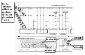
If the same symptom occurs a second time, or if the vehicle has a prior history of front oxygen sensor-related DTC concerns, replace the four terminals between the PCM and the front oxygen sensor heater terminals as shown in Fig. 7, and in the Replacement Procedures section of this TSB.
Service Procedure: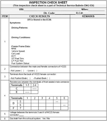
Inspection Checklist (First-time condition):
1. Retrieve any heated oxygen sensor-related DTCs(P0030, P0031, P0032) with GDS. Record the DTCs, symptoms, driving patterns, driving conditions and freeze-frame data on the checksheet.
2. Verify that the male connector of the front oxygen sensor is completely inserted into the female connector end and record results on the checksheet. If the connection between the male and female connectors is loose, reconnect them completely and clear the related DTCs; no further action is required. 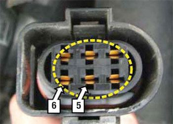
3. Verify that the terminals in the female connector of front oxygen sensor are not pushed back (see Fig. 8) and record the results on the checksheet. If required, fully seat and lock any loose terminals into each terminal cavity and clear the related DTCs. If the MIL illumination has been caused by the loose terminals, no further action is required.
4. Measure the resistances between the terminals of the male connector of front oxygen sensor at room temperature (70° F) (see Fig. 9) and record them on the checksheet.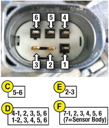
Normal resistance range:
C: 2~4 Ω
D: Greater than -1 MΩ
E: 100~4500 Ω
F: Greater than -1 MΩ
If any resistances are out of these specified resistance ranges, replace the front oxygen sensor.
5. Measure the voltage between terminals 5 and 6 of the harness side of front oxygen sensor with the vehicle running and record it on the checksheet.
Normal voltage range: 12-14.5V (Voltage may fluctuate until warm)
6. Check for leaks in the exhaust manifold oxygen sensor fittings, exhaust front pipe or catalytic converter and record results on the checksheet. If there is a gas leak, repair the exhaust system and recheck the gas leak.
Note: If a vehicle returns (check repair history) with DTCs P0030, P0031 or P00323 after the inspection listed above, proceed with the front oxygen sensor and PCM terminal replacement procedure shown below.
Replacement of Front Oxygen Sensor and PCM Terminals:
1. Record preset radio stations and disconnect the battery negative cable.
2. Remove the engine cover.
3. Disconnect the front oxygen sensor connector.
4. Remove the front oxygen sensor female connector and bracket.
5. Remove the connector from the bracket. Be very careful not to damage the connector attaching clip. The connector must be secured after repair for proper oxygen sensor operation.
6. Remove the back cover from the connector by lifting the two tabs.
7. Peel back the tape off the connector wiring harness 3-4 in.
8. Remove the white plastic terminal retainer from the connector.
9. Remove the two terminals 1 (blue with orange stripe) and 4 (white) using a two-blade terminal removal tool. Locations of terminals 1 and 4 are shown in Fig 10.
Recommended terminal removal tools are: Blue-Point P/N-TT1212 from kit P/N TT12KT or Mac Tools P/N TT93060 from kit P/N-TT96030. 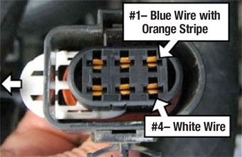
Note: Bend the ends of the tool blades in slightly to fit into the two release holes at the sides of each terminal.
10. Cut the terminal 4 wire (white) 2-2.5 in. from the terminal.
11. Prepare the new same-color wire with the oxygen sensor connector terminal (larger than PCM-side terminal) and slide the heat-shrinking tube onto the wire allowing room to splice and solder.
12. Strip the ends of wire insulations, put a splice clip over the exposed wires and crimp it. Solder the splice with low-temperature solder being careful not to overheat the wires or heat-shrinking tube.
Note: Verify that the splice clip holds the exposed wires securely.
13. Slide the heat-shrinking tubes over the splice clips and apply heat to them.
Note:
– Heating temperature required: 750° F
– Center the heat-shrinking tube over the crimped connection and heat it until glue melts out of each end.
– Be careful not to damage the tube and the wire insulation from excessive heating.
14. Repeat steps 10 through 13 on the terminal 1 wire (blue with orange stripe).
15. Turn the new terminal in the proper direction and insert into each terminal cavity. Install the white plastic retainer wrap electrical tape around the harness and connector transition and install the connector and engine cover in reverse order of removal.
– Terminal 1 (blue with orange) wire goes on connector lock side;
– Terminal 4 (white) wire goes on connector mounting clip side.
16. Disconnect the hood release cable for better access. Disconnect the PCM harness wire tie clip at the top of the PCM bracket. Disconnect the larger of the two PCM connectors from the PCM. Pull the connector down to allow access to work.
17. Cut the small tie strap and remove the tape from the harness above the PCM connector down and away from the harness. Caution: Don’t pull up on the cover or the tabs will break.
18. Remove the blue terminal pack retainer from the connector.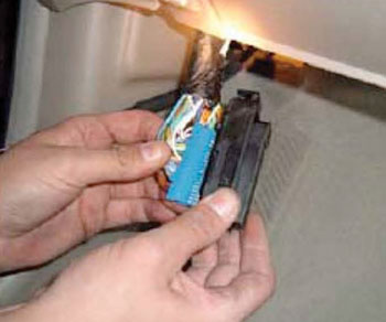
19. Release the two lock tabs at the top of the blue terminal pack and slide out of the main connector. See Fig. 11.
20. Release the terminal lock tabs on the side of the terminal pack to remove terminals 19 (white) and 41 (blue with orange stripe). The terminal lock tabs are on the side of the silver terminal located through the small windows in the side of the terminal pack.
21. Repeat steps 10 through 13 on the 19 and 41 terminals.
Notice:
– Prepare the two PCM terminal wires from the repair kit.
– To avoid mixing up the two PCM wires, it may be helpful to replace the terminals and install them in the PCM connector one at a time.
22. Fit the new terminals into each terminal cavity and securely install the connector pack into the connector housing. Install the blue terminal pack retainer removed in step 18. Wrap electrical tape around the wiring harness and place a small wire tie around the connector cover to secure it to the harness.
23. Slide the wiring harness down 0.8 in. through the wire tie at the PCM bracket to relax the bend at the PCM connector and reconnect it. Reinstall the wire tie clip in the PCM bracket.
24. Connect the battery cable, reset the radio stations and reinstall the hood release cable.
25. Start the engine and verify proper operation with no MIL on.
Courtesy of ALLDATA.