Nothing upsets pernickety homeowners more than driveway stains caused by oil leaking from the vehicles of visiting friends and family. However, many of the vehicles that suffer oil leaks can be cured. It just takes a bit of detective work to locate the leak source and some labor time to make the repair.
In essence, those technicians who take on leaking engine work aren’t only providing environmental repairs to the vehicle, they’re repairing relationships among family members and their meticulous relatives.
SOLUTION TO A LEAKING GM VORTEC
Some repair shops reported having had GM vehicles in their bays to service Vortec engine oil leaks, specifically on 2003-’06 GM 4.8L, 5.3L, 5.7L, 6.0L and the 7.0L engines. Most of the complaints involved oil leaking from the drivetrain area of these engines.
Upon a closer look, this oil leak is usually coming from the rear cover gasket area and the condition, according to engine specialists, may be the result of engine block porosity on the sealing surface.
 Repair Procedure
If the leak has been identified as coming from the rear cover gasket area, remove the cover area and inspect the cylinder block for any indications of porosity in the sealing areas.
If porosity is found anywhere on the sealing surface, use RTV P/N 8-12778-521-0 to fill in these areas.
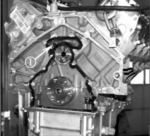
Next, wipe a small amount of the RTV sealant onto the surface using a plastic scraper to fill in the porosity holes on the mating surface of cylinder block. Remove any excessive RTV that may have been applied, especially from the high-pressure oil passage as shown with the arrow in Photo 1.
Allow the RTV to cure 10 minutes before installing the rear cover. When installing the rear cover, tighten the engine rear cover bolts to 18 ft.-lbs.
LEAKING CRANKSHAFT OIL SEALS ON SUBARU ENGINES
You may encounter a 1996-’99 Legacy, or a 1998-’99 Impreza or Legacy with a 2.5L engine, with a leaking or dislodged front crankshaft oil seal. It may be necessary to remove the oil pump and examine the rear sealing plate of the oil pump.
In some cases, the front seal will have been replaced, only to have the customer return a short time later with the same complaint. In these cases, the seal is either leaking again, has been pushed out, or it’s leaking from the weep hole. The screws holding the rear sealing plate on the oil pump may have come loose. This allows oil to exit the pump rotor area and get into the oil pump body where it’s pressurized. This pressurized oil pushes on the seal, causing it to leak or push it out of its mounting.
Courtesy of Mitchell 1.
For more information on Mitchell 1 products and services, automotive professionals can log onto the company’s website at www.mitchell1.com.
SAAB CRANKCASE OIL LEAK
Under certain operating conditions, the crankcase ventilation through-flow may be inadequate and can cause oil leakage. The leakage most commonly occurs at the joint between the timing cover, cylinder block and cylinder head as well as the crankshaft seal. Also note that efficient crankcase ventilation is also very important for avoiding increased oil consumption.
The gasket replacement/resealing must be performed only if the oil leakage does not cease after the below procedure is performed.
Affected Vehicles: Saab 9-3 M99-M03 with engine variant B205 and B235
Required Parts: 59 62 428 (CA: 30593216) — Renovation kit, crankcase ventilation with the following contents: check valve/ reducing valve; bleed nipple; and rubber plug.
Note: The check valve/reducing valve does not stop the air flow in the opposite direction. The valve facilitates different flows in the relevant direction within the circuit.
Parts, If Necessary:
• 91 86 875 (CA: 30570590) – Hose for turbo inlet pipe;
• 91 88 806 (CA: 30581025) – Hose for camshaft cover; and
• 93 99 973 (CA: 30585634) – Hose with check valve (small circuit).
Service Procedure
1. Disconnect the battery negative cable.
2. Remove the upper engine cover.
3. Remove the oil trap’s two upper hoses. See Figure 1, #3.
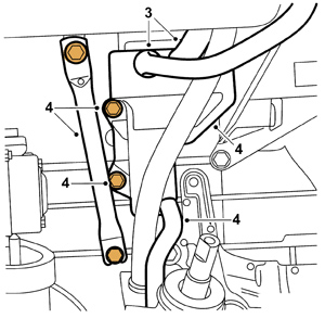
4. Raise the car and remove the lower hose to the oil trap. Remove the stay to the intake manifold and oil trap. If necessary, disconnect the generator positive cable. See Figure 1, #4.
5. Turn the oil trap as indicated in Figure 2 and drill the hole with the extra restriction up to 10 mm.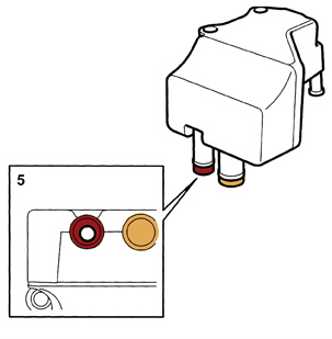
6. Thoroughly blow-clean the oil trap.
7. Fit the oil trap, the lower hose to the oil trap and the stay to the intake manifold. If necessary, connect the generator positive cable. See Figure 3, #7.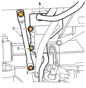
8. Lower the car.
9. Connect the oil trap’s upper hoses (if necessary, fit new hoses to the oil trap). See Figure 3, #9.
10. Remove the small circuit’s hose from the camshaft cover.
11. Connect the enclosed rubber plug where the small circuit was fitted in the camshaft cover. See Figure 4, #11.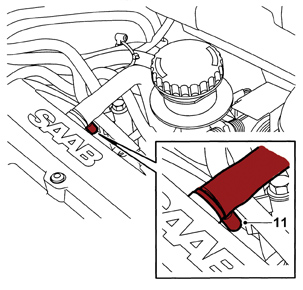
12. Remove the oil filler pipe.
13. Drill a 7 mm hole and fit the bleed nipple on the oil filler pipe as shown in Figure 5.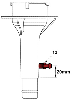
Note: It’s important that the small hole in the bleed nipple points down in the oil filler pipe. Fit the nipple as far in to where the threads become visible on the inside in order to prevent the dipstick from jamming. It’s very important that the nipple’s fitting angle complies with Figure 6 so that the oil filler pipe can be refitted.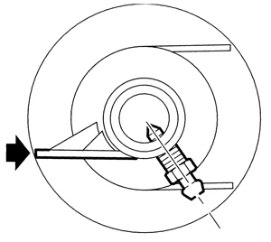
14. Check the operation of the check valve on the small circuit using 30 14 883 pressure/vacuum pump, and replace if necessary.
Note: Observe the arrow’s direction on the check valve.
15. When fitting the small circuit’s hose on the oil filler pipe’s bleed nipple, pull the hose between the cable ducting and the fuel rail.
16. Fit the oil filler pipe.
Note: Make sure that the hose is securely fitted on the nipple after the oil filler pipe has been fitted.
17. Cut the hose to the turbo inlet pipe to a height level with the intake manifold. See Figure 7, #17.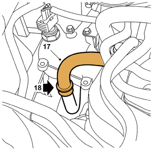
18. Fit the check valve/reducing valve. See Figure 7, #18.
Note: The direction of the arrow must be pointing upward (from the oil trap to the turbo). Also note that the check valve/reducing valve doesn’t stop the airflow in the opposite direction but only reduces the airflow.
19. Fit the upper engine cover.
20. Fit the battery negative cable.
21. Set the correct time and date in the service information display.
Courtesy of Mitchell 1.
For more information on Mitchell 1 products and services, automotive professionals can log onto the company’s website at www.mitchell1.com.