This bulletin involves rotating all engine exhaust valves, replacing the valve spring retainer locks with a new design to increase valve rotation at lower rpm, inspecting/replacing the MAP sensor (as necessary), and decarbonizing the combustion chamber.
Models: 2004-’06 Pacifica (CS) and 2005-’06 Chrysler 300/ Magnum/Charger (LX)
Note: This bulletin applies to CS models built after Feb. 1, 2004 (MDH 0201XX) equipped with a 3.5L engine (Sales Code EGN).
Symptom/Condition
The customer may experience occasional engine misfire (rough-running engine) during certain
vehicle operating conditions.
In addition, MIL illumination may also have occurred due to DTC P0300 – Multiple Cylinder Misfire. Various single cylinder misfire DTCs may also be present. If the frequency of misfire is high, the powertrain control module (PCM) may place the engine in “limp-in” mode.
The misfire condition may be caused by one or more engine exhaust valves that are slow to close due to a buildup of carbon on the valve stem.
Diagnosis
1. This condition may occur when the engine is not allowed to run at engine rpms that are greater than 3,500. At 5,000 rpm or higher, the engine exhaust valves will rotate if not impeded by high carbon deposits. Low engine rpms and high carbon deposits are associated with short-trip driving where the engine is not allowed to fully warm to normal engine operating temperatures.
Cold ambient temperatures will increase engine warm-up time and increase the likelihood of carbon deposit buildup on the stem of the engine exhaust valve. Fuel detergent quality may also contribute to the condition; the customer may want to try a different brand of fuel.
2. Verify that the engine misfire condition is not caused by faulty engine mechanical or electrical components.
3. If the engine mechanical and electrical systems are operating properly, perform the Repair Procedure.
Repair Procedure
Valve Rotation:
1. Relieve the fuel pressure.
2. Remove the upper intake manifold.
3. Remove the cylinder head cover(s).
4. Remove the rocker arm and shaft assembly.
5. Clean and mark the tip of each exhaust valve stem at the 12 o’clock position with a paint marker. The paint mark will be used later to assist with determining the amount of valve rotation.
6. Remove the spark plugs.
7. Rotate the crankshaft clockwise, until the number 1 piston is at Top Dead Center (TDC) on the compression stroke.
8. Install the compression tester spark plug adapter in cylinder #1 spark plug hole. With the air hose attached to the spark plug adapter, apply 620.5 to 689 kPa (90 to 100 psi) air pressure. This is to hold the valves into place while servicing the components.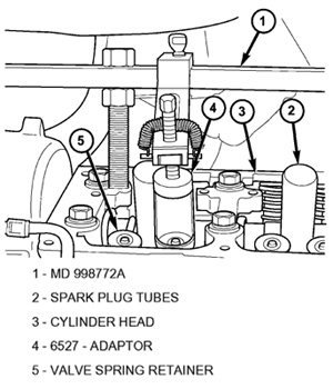
9. Using a valve spring compressor tool (MD 998772A) with the valve spring adapter (6527 or equivalent), slightly compress the exhaust valve spring to release tension against the valve and valve spring retainer (see Figure 1).
10. Remove the valve spring retainer locks and discard the locks.
Note: It is important that the valve rotation section of this repair procedure be performed.
Caution: Only grab the valve stem tip, being careful not to cause damage.
11. Using needle-nose pliers, grab the tip of the valve stem and rotate the exhaust valve 90° (move the mark to the 3 o’clock position).
12. Install two new valve spring retainer locks (P/N 53022277AA).
13. After installing the locks, release the tension on the valve spring and verify proper installation.
14. Remove Special Tool MD 998772A (1) and the spark plug adapter tool.
15. Repeat steps 7-14 on the remaining five cylinders using the firing sequence 1-2-3-4-5-6. Make sure the piston is at TDC in each cylinder of the exhaust valve spring retainer lock that is being removed. When all the exhaust valves have been rotated 90° and all the exhaust valve spring retainer locks have been replaced, proceed to the next step.
16. Install the rocker arm and shaft assembly.
17. Install the cylinder head cover(s).
18. Install the upper intake manifold 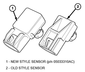
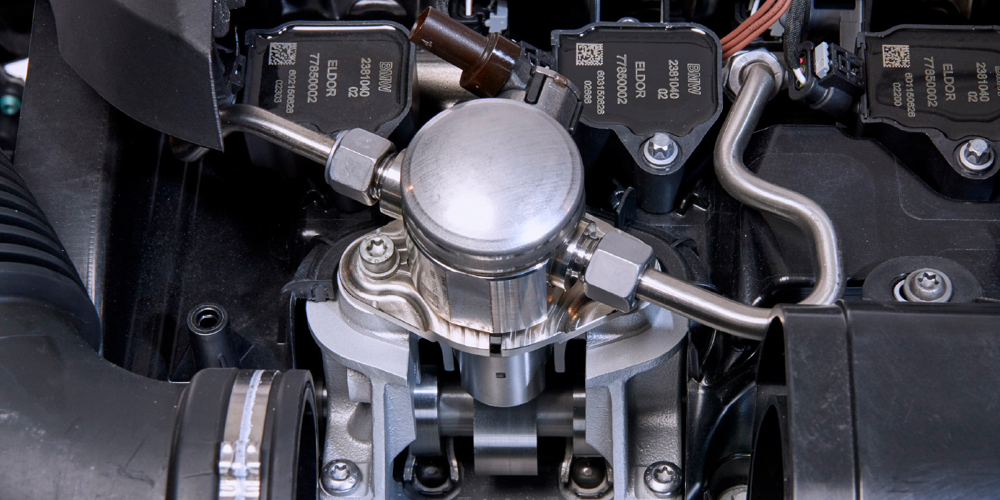
MAP Sensor Inspection:
1. Inspect the MAP sensor — Figure 6 for LX models or Figure 3 for CS models.
a. If the MAP sensor is the new style, no further action is necessary for the MAP sensor. Proceed to Decarboning Combustion Chamber and Valves.
b. If the MAP sensor is the old style, proceed to the next step.
2. Replace the MAP sensor with P/N 05033310AC for LX models or P/N 04896003AB for CS models. If the vehicle is a CS model, be sure the new sensor opening is facing a downward direction when installed and only use one fastener.
When complete, proceed to Decarboning Combustion Chamber and Valves.
Decarboning Combustion Chamber and Valves:
Caution: Do not use the Premium Air Intake Cleaner provided with kit 05174566AA for this service action.
Note: Use both fuel tank additives.
1. Pour the Premium Fuel System Cleaner from kit P/N 05174566AA and Combustion Clean P/N 05183546AA, into a full fuel tank.
2. Start the vehicle’s engine and allow it to reach normal operating temperature.
3. Disable the fuel pump by removing the fuel pump relay.
4. Disconnect the fuel supply line quick disconnect fitting from the fuel rail.
5. Install the appropriate adapter, either #31814 or #31815. Be sure to engage the adapter completely (push until a “click” is noticed).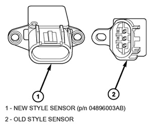
6. Pour the Premium Combustion Chamber Cleaner from kit P/N 05174566AA, into the cleaning
canister.
7. Suspend the fuel injector cleaning apparatus under the hood. The regulator knob must be fully counterclockwise to the off position. Connect the cleaning apparatus service hose to the supply adapter.
8. Turn the regulator knob clockwise to the recommended cleaning pressure (58 psi). Be sure there are no leaks before starting the engine.
9. Start the engine and run at normal idle (or fast idle, 1,200-1,500 rpm, to shorten service time) until the product has been used up and the engine stalls.
10. When the engine stalls, turn the ignition off.
11. Disconnect the cleaning apparatus and adapter.
12. Reconnect fuel line and the fuel pump relay.
13. Turn the ignition key to the on position to energize the fuel pump. Check for leaks. Start the engine and run for at least 2 minutes to clear the fuel system of any residual product.
14. Using the DRBIII or the Star-SCAN, erase any engine DTCs.
Road Test:
1. In a safe vehicle operating location that will allow the vehicle to be driven safely and at the posted speed limit, accelerate the vehicle until the engine reaches 4,500 rpm.
2. Hold the engine speed at this rpm for 15 seconds.
3. Slow down and, in a safe location, pull to the side of the road. Allow the engine to idle for five seconds.
4. Repeat steps 1 through 3 five more times.
Courtesy of ALLDATA.