Since model year 2003, a growing number of domestic and import vehicles have been built with a new onboard communications protocol called CAN (Controller Area Network). CAN is essentially an engineering standard for how computers and modules talk to one another via the serial data bus in a vehicle’s wiring system. It’s a high-speed standard designed for powertrain control modules, antilock brakes and stability control systems.
The CAN protocol was created back in 1984 by Robert Bosch Corp. in anticipation of future advances in onboard electronics. The first production application was in 1992 on several Mercedes-Benz models, but CAN is now being used on more and more new vehicles. By 2008, all new vehicles sold in the U.S. will be required to have a CAN-compliant onboard diagnostic system. But you won’t have to wait until then to encounter CAN diagnostics because many of the early applications are already out of warranty and may be coming into your shop now.
Geek-Speak
If you’re not up to speed on the latest electronics and don’t know a data bus from a school bus, diagnosing CAN systems will be a challenge. Even so, you don’t have to be an engineer to perform basic diagnostics on CAN-equipped vehicles because the problem-solving is essentially the same as current OBD II vehicles. The only difference is that you need a CAN-compliant scan tool to read the vehicle serial data. Most current generation scan tools don’t have the right hardware or software to talk to CAN-equipped vehicles. Some scan tools have the right hardware, but must be upgraded with new software to handle the faster communication rates and to decipher the CAN messages.
Like many current vehicles, information in a CAN-equipped vehicle is shared over a serial data bus. The bus is the circuit that carries all the electronic chatter between modules (nodes). The bus may have one wire or two. If it has two, the wires are usually twisted to cancel out electromagnetic interference. The speed at which the bus carries information will vary depending on the “class” rating of the bus as well as the protocol to which it conforms.
~ A data bus with a “Class A” speed rating is a relatively slow, low-speed circuit that typically carries less than 10 kilobits (10 Kbps) of information per second. A data bus that operates at Class A speeds is limited to simple command functions like operating power mirrors, power seats, power widows, power door locks, remote trunk releases and lights.
~ A data bus with a “Class B” rating, by comparison, may operate from 10 Kbps up to 125 Kbps, depending on the operating protocol (SAE J1850 or Europe’s ISO 9141-2). This is fast enough to carry more complex information and time-sensitive data. Systems that may share a data bus with a Class B rating include electronic instrumentation, electronic transmission controls, security systems and climate control.
~ Class C is currently the fastest data bus rating. Class C systems can operate at speeds up to 1 megabit per second, which is up to 100 times faster than a typical Class B data bus. Many of the vehicles that are currently using a Class C data bus are operating at speeds of around 500 Kbps, which is fast enough for powertrain control modules, air bag modules, and fast-acting antilock brake and stability control systems. Down the road are even faster systems, with “Class D” ratings of over 1 megabyte per second. And some applications such as onboard entertainment systems require even higher speed audio and video streaming.
One thing to keep in mind about the CAN standard is that CAN (as well as other protocols such as SAE J1939, GMLAN, OBD II, SAE J1587 and LIN) has more to do with the way information is formatted, transmitted and received than how fast it is sent. This means the automotive engineers who design the onboard electronics for CAN-compliant vehicles are free to choose any operating speed they want (up to 1 megabit per second) as well as the type of bus conductor (one wire, twisted paired wires or a fiber optic cable). On most cars today, a high-speed data bus is needed to handle the volume of information going back and forth between all the onboard electronics.
In 1995, GM introduced its own “Class 2” data bus to handle communication between modules. The system ran at a speed of 10,400 bits per second (10.4 Kbps), which was more than adequate for vehicles a decade ago. In 2004, GM moved to their next generation data bus system, which they called “GMLAN” (GM Local Area Network). Introduced on the Cadillac XLR and Saturn Ion, GMLAN added the capability to operate at two speeds on two separate buses: a low-speed (33.33 Kbps) bus and a high-speed (500 Kbps) bus.
The low-speed side of the GMLAN system operates on a single-wire bus to handle body-related control functions, while the high-speed bus uses two wires to carry data between the powertrain, transmission and antilock brake modules. A “gateway” node connects the high-speed bus and low-speed bus, and allows information to be shared back and forth. For example, the radio (which is connected to the low-speed bus) may adjust volume based on engine speed and vehicle speed (from the high-speed bus) to offset road noise.
Mercedes also uses several different bus speeds on its vehicles. Depending on the application, there may be a high-speed 500 Kbps CAN-C bus for the powertrain, transmission and ABS modules, and a slower speed 83 Kbps CAN-B bus for the body control functions. On some Mercedes cars, there may be as many as 30 modules on the CAN-B bus. Up to model year 2002, all communication between the CAN-C and CAN-B bus went through the electronic ignition switch (EIS) module. After 2002, a new “gateway” module handles the inter-bus communications as well as onboard diagnostics via a CAN-D bus.
How Data Is Sent and Received
If your eyes haven’t glazed over yet with all this geek-speak, here’s how data is handled on a CAN-compliant system. Every module (node) that is attached to the data bus network is capable of sending and receiving signals. Each module has its own unique address on the network. This allows the module to receive the inputs and data it needs to function, while ignoring information intended for other modules that share the network. When a module transmits information over the network, the information is coded so all the other modules recognize where it came from.
Data is sent as a series of digital bits consisting of zeros and ones. If you looked at the data on a scope, you would see a square wave pattern that changes between a high and low voltage reading. The low voltage reading usually corresponds to the zero while the high voltage reading corresponds to the one. The actual voltage readings will vary depending on the application and protocols the vehicle manufacturer is using, but most operate in the 5 to 7 volts range.
The CAN standard requires a “base frame” format for the data. What this means is that for each distinct message sent or received by a module on the network, there is a beginning bit (called the “start of frame” or “start of message” bit), followed by an “identifier” code (an 11-bit code that tells what kind of data the message contains), followed by a priority code (“remote transmission request”) that says how important the data is, followed by 0 to 8 bytes (1 byte equals 8 bits) of actual data, followed by some more bits that verify the information (cyclic redundancy check), followed by some “end of message” bits and an “end-of-frame” bit.
Still with me? There’s more! One of the tasks of any network system is to keep all the messages separated so they don’t collide and garble one another. Usually the body control module or instrument cluster module is assigned the task of managing the network traffic. When it sees a message coming over the bus, it looks at the first bit in the data stream. If the bit is a zero, the message is given priority over the others. This is called a “dominant” message. If the first bit is a one it is given a lower priority (a “recessive” message). Thus, the highest priority messages always get through to their intended destinations but the low-priority messages may be temporarily blocked until the traffic eases up.
Real-World Diagnostics
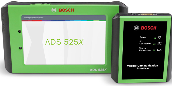
So what does all of this have to do with diagnosing vehicle faults? For one thing, you need a special CAN-adapter module to use a Tech 2 scan tool on a newer CAN-compliant GM vehicle. All the automakers are currently in the process of upgrading or replacing their current scan tools with newer CAN-compliant tools (some of which will be PC-based unlike today’s dedicated hand-held scan tools). As for aftermarket scan tools, some are CAN-compliant and others are not, so check with your scan tool supplier before you buy. CAN-compliant vehicles are just as vulnerable to electronic faults as older vehicles. Though CAN systems use fewer wires and fewer connectors (to save weight and cost), they also use more modules and more complicated modules. Problems can occur if module connectors become corroded or loose, if wires become grounded, shorted or break, or system voltage is below specifications. Some modules may even forget their settings or locations if the battery is disconnected or goes dead.
On some Chrysler minivans, for example, the automatic climate control system will quit working if battery power is lost. This happens because the electric stepper motors that control the position of the blend doors forget their locations. The system has to be put into a “relearn” mode to re-establish all the motor locations and settings.
One of the features of CAN and other network systems is that modules can send and receive “OK” signals to let the main control module know if they are working or not. In theory, this makes diagnostics easier. On the other hand, it also means that one misbehaving module may generate enough noise to disrupt the entire network causing a complete shutdown of the vehicle!
When a serial bus communication problem occurs, it will usually set a “U” diagnostic trouble code and turn on the Malfunction Indicator Lamp. Depending on the fault, the vehicle may or may not start, or it may only operate in a “limp-in” mode with limited capabilities. Loss of communication between the engine controller and transmission controller (code U1026 on a GM, for example) may put the transmission into a limp-in mode where it will only operate in one or two gears.
Loss of communication codes may indicate a wiring problem on the bus, or a fault with a module. Isolating the fault may require unplugging modules one at a time until the fault is found. Just remember that all modules on a bus network need three things to function properly: power, ground and a serial data connection.
When diagnosing bus or module communication problems, you usually start by checking for voltage at the module, then the ground connection and finally the data line. If all three are good but the module isn’t working, the module needs to be replaced.
On GM applications, a code U100 or U1255 means a general loss of communication on the data bus. With a Tech 2 scan tool, you can go to Diagnostic Circuit Check, then Message Monitor to see a list of active modules and compare it to the list of modules that are supposed to be on when the key is on.
To minimize the parasitic current drain on the battery when the vehicle is off, a “sleep” signal is sent to the modules on the network. Some may remain on for a short period of time after the ignition is switched off (air bag module, for example), and some may never go to sleep (anti-theft module and keyless entry receiver, for example) but most are put into a sleep mode to save battery power. If the sleep signal is never sent, or a module fails to recognize the sleep signal, it may remain active and pull power from the battery. Depending on the current draw, this may run down the battery if the vehicle sits for a period of time.
|
A Growing List of CAN Applications:
2003 Ford Excursion 2003 Ford F-250 and F-350 2003 Ford Focus and Thunderbird 2003 General Motors Saturn ION 2003 Lincoln LS 2003 Mazda 6 2003 SAAB 9-3 2004 Buick Rendezvous 2005 Audi A4 and A6 |
|
Delage Styling and Design
In Richard S. Adatto and Diana E. Meredith’s latest book, Delage Styling and Design La Belle Voiture Francaise, we see the celebration of the golden era when the extraordinary Delage chassis joined forces with the most distinguished French stylists and coachbuilders of the age. Car enthusiasts can now enjoy a book written in English about the marque preferred by the rich and famous from 1929 to 1953. The book provides an account of the beginnings of the company headed by Louis Delage and his team of engineers, and touches upon its early racing history when driver Robert Benoist won the trophies that made the car famous around the world. Subsequent chapters describe the styling and design of the stunning cars built at the height of the “French Style,” when the Delage chassis was dressed by the best of the best. Examples of each design are described and photographed, with images taken at the time of their construction and present day photographs of beautifully restored cars. Reproductions of lovely period drawings and sketches also are incorporated, and the book includes an appendix with 14 pages of technical information and tuning specifications. Book Notes: |