Keeping the angles in line with Ackermann
Most people consider the common tire rod to be low tech. But, when you consider how front suspensions have evolved from straight axles to independent designs, the tie rod has had to adapt to new angles and geometry.
Keeping it on the road was simple with the straight axle. A beam axle with two spindles attached with king pins set at an angle called “king pin inclination.” The angle maintains the turning radius and passes through the center of the tire contact patch. A drag link and tie rod connects the spindles to the steering gear. The wheels are turned at two different angles with the inside wheel turned more than the outside to prevent the inside tire from scrubbing and causing tire wear. 
A fellow by the name of Ackermann in 1881 patented the geometry that allowed the inside and outside wheels to turn at different angles.
There are a lot of four-wheel drive SUVs, light- and medium-duty trucks that still use a straight front axle. Everything is the same except the axle has a differential and universal or CV joints to allow the wheels to turn.
In 1934, GM made its first try at an independent suspension with “Knee Action” suspension on the Chevrolet. Five years later, GM tried again with the double wishbone independent front suspension. This brought a new series of challenges to the design of steering linkage.
The independent suspension wishbones, that are now called control arms, move in an arc from their attachment to the chassis. The upper and lower control arms are of different lengths to make the wheel and tire contact patch maintain the same position as the suspension moves. The term king pin inclination is now called “steering axis inclination” (SAI). A strut suspension does the same by aligning to the SAI to compensate for the lower control arm. Straight axle steering was modified for the independent suspension by moving the steering gear sector to a vertical position and attaching the pitman arm and drag link to an idler arm. The tie rod was replaced with two tie rods and attached to the drag link. This modification became what is called a conventional steering gear.
Bump Steer: What a Drag
The tie rods of the conventional steering gear move in an arc just as the control arms. When a wheel hits a bump, the movement of the tie rod will cause the wheel to tow out. This is referred to as bump steer. The same occurs when the chassis rolls in a corner. This can be referred to as under steer. The length and location of the tie rods and the arc they move in are designed to minimize bump and roll steer.
Conventional Steering Gear Operation
The steering gear can be a worm and sector or a recirculating ball nut and sector.
The sector is a section of a gear that turns a shaft. Attached to the sector shaft is a pitman arm. The pitman arm is connected to a fixed joint located in the drag link. The drag link is connected to the idler arm, which has two fixed joints. A fixed joint has a tapered or straight seat that makes the idler arm and the pitman arm move in the same plane. The drag link moves in a parallel plane to the pitman arm and idler arm. The tie rod ends are ball joints connected to the steering knuckle. The tie rod is attached to the drag link by a fixed joint called a center link. The center links maintain the tie rod’s position to the drag link.
There are variations on the conventional setup. The most notable are the Chevrolet Astro and GMC Safari mini vans, where there are two idler arms that support the drag link. The steering gear pitman arm is mounted in a vertical position and mounted to a second drag link.
Conventional Steering Gear Inspection
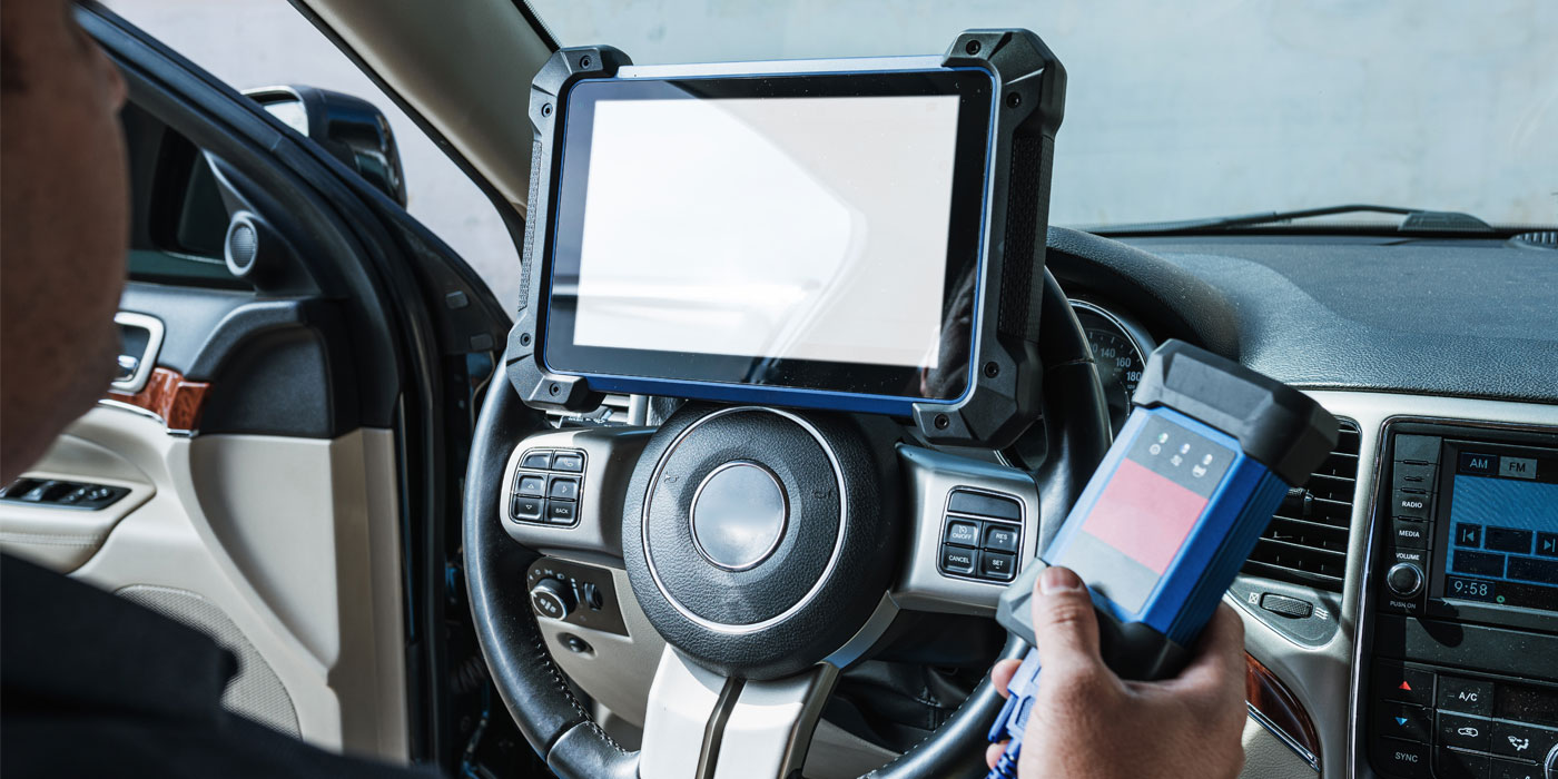
The best way to inspect the steering system is with the vehicle on the ground or on the turn plates of an alignment rack.
 Inspecting the Right Way
The inspection should begin with the pitman and idler arms. They should remain in the same plane as the wheels are turned from lock to lock. In the case of the mini van, the same applies to the second drag link. Some idler arms have a specified end play that is measured with a spring tension gauge.
Next is the steering gear. Check for leaks at the sector shaft. If these components are OK, check the play in the steering wheel. Both the worm and sector and recirculating ball have a thrust adjusting screw. A rule of thumb says that there should be one to two inches of free play in the steering wheel and no binding when the wheel is turned from full lock to lock. There is a thrust adjusting screw located above the sector. Adjusting the screw can change the amount of free play in the steering gear. It is important to follow the recommended adjustment procedures, as some gears cannot be adjusted in the vehicle.
Rack and Pinion Operation
The hydraulic power assist piston is part of the rack and the tie rods are attached directly to the rack gear using a threaded housing to hold the ball. In these applications, the tie rods are connected to the rack. It takes a special tool to remove the ball joint from the rack without damaging a seal on the power cylinder. A variation of the rack and pinion steering gear is the center take off. The tie rods are attached to the center of the rack and the power assist cylinder is moved to the end of the rack. The tie rods extended length of the center take off is designed to reduce the amount of bump and roll steer. The rack has an adjustment for the pinion gear to rack thrust clearance. The adjuster is made up of a shoe and adjusting mechanism located below the pinion. It has the same function as the thrust screw for a worm and sector or ball nut and sector.
Rack and Pinion Inspection
Most of the racks produced today are power assisted. The tie rods are directly connected to the rack gear assembly.
A ball joint connects the tie rod to the rack and a tie rod end, which is also a ball joint that attaches to the steering knuckle. The center take off steering gear uses rubber bushings to attach the tie rods to the center of the rack housing.
 Tie Rods
Between 45 and 60, a vibration and shimmy comes and goes. Is it the tie rods or the steering linkage? The shimmy is most probably the tie rods. If the vehicle wanders and requires constant steering corrections, the linkage or steering gear should be the cause. Let’s start with a conventional steering gear. The tie rod ends are ball joints connected to the steering knuckle. There should not binding or end play. The center links should remain parallel to the drag link. The best way is a two-person operation. One person should turn the steering wheel from lock to lock while the second observes the tie rod end and center link. The best place to start is the passenger side as it is the closest to road splash and curb hits. If it is a rack and pinion steering gear, it’s the tie rods.
There are two different types of joints. The inner tie rod end is a ball joint connected directly to the steering rack. To replace an inner joint requires special tools to remove the nut and socket from the rack. The tool prevents damage to the power piston seals. The outer tie rod end is the same as a conventional steering gear and is connected to the steering knuckle. The center take off rack and pinion gear requires that you use a special tool and lubricant to install new OE bushings. The proper lock plate and cover washers must be installed properly to prevent damage to the rack housing.
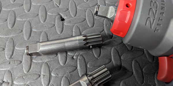
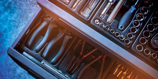
Right Tool
There are a lot of tools for working on steering linkage. The oldest is the pickle fork, used to separate the joint from the linkage. It works, but it can damage a sealing boot. There are pullers that can cause less damage, but cost more. If you are not into special tools, turn the nut over and don’t force it. Get a bigger hammer.
There are more and more vehicles with four-wheel independent suspensions where the rear suspension has the same components as the front. The only difference is most will not have a steering gear. As these vehicles age, the need for maintaining and repairing these suspensions will grow.