 By Sergey Vorsin, Vasyl Postolovskyi and Olle Gladso
Contributing Writers and Instructors at Riverland Technical and Community College in Albert Lea, MN
The first time I encountered the P2716 Pressure Control solenoid “D” Circuit DTC on a Toyota Corolla, I didn’t attach much importance to it. It was just one of many possible faults we, as automotive technicians, face every day. However, as I started to see this DTC pop up frequently, I became interested in what the possible causes could be.
I conferred with some technicians who regularly diagnose and repair automatic transmissions and it was confirmed that a significant number of these failures existed. The OEM has also noted the large number of this particular trouble code failure, as is evidenced in a TSB. For these reasons, I believe the solution of this problem will be of interest to a wide range of our readers.
Discussion
The journey started when I came across another Toyota Corolla equipped with the 1ZZ-FE engine. This vehicle would occasionally set the P2716 DTC. The error was sporadic – anywhere from a couple of hours up to several days could pass before the failure recurred.
Automatic transmission technicians told me that it was necessary to remove and disassemble the transmission to repair this problem. They also said that the problem was caused by a malfunctioning solenoid “D” and that, unfortunately, you could only get to the solenoid by removing the transmission.
Of great concern to me was the amount of work necessary and the uncertainty as to if replacing the solenoid would actually repair the issue. The P2716 Pressure Control Solenoid “D” DTC is a circuit or electrical code and seemed to be the only DTC that would consistently appear.
The P2718 Pressure Control Solenoid “D” Control Circuit/Open and/or P2719 Pressure Control Solenoid “D” Control Circuit Range/Performance codes did not set. Also, if the solenoid itself had failed, wouldn’t we sometimes see P2714 Pressure Control Solenoid “D” Performance/Stuck Off or P2715 Pressure Control Solenoid “D” Stuck On DTCs?
Diagnosis
The preliminary analysis of the problem is one of sporadic failure, and most likely electrical rather than mechanical. It should be mentioned that it is possible, however, for an occasional mechanical seizing of Solenoid “D” to cause an increase of current consumption, setting the P2716 DTC. If the failure were to occur in the control or the power circuits, the PCM should set P2718 and/or 2719. These DTCs do not set, so it is reasonable to assume that the actual circuits are OK.
To properly diagnose this problem, it is necessary to use an automotive diagnostic oscilloscope/engine analyzer that can measure and record both voltage and current simultaneously with sufficient resolution and speed. For me, the most suitable tool for this type of diagnosis is the USB Autoscope IV, which combines compactness, performance and ease of use.
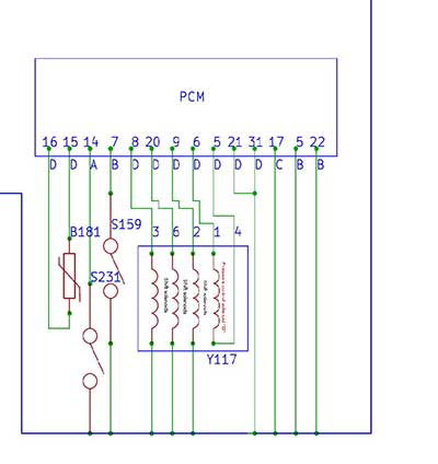
As can be seen in Figure 1, solenoid “D” is connected to terminals 1 and 4 of the connector. Notice that the PCM supplies both power and ground to the pressure control solenoid through these two terminals. Contrast this with the shift solenoids that have a fixed ground and the PCM provides a power to operate them. Note that at this point, we do not know which terminal is the power supply and which terminal is the ground or low control for the pressure control solenoid.
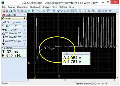
The oscilloscope was connected between ground and terminal 4 on the transmission connector. The waveform obtained from terminal 4 can be seen in Figure 2. You can see that the voltage on the control or ground side does not drop below 4.5V, and that the control voltage is unstable.
Based on the waveform, it is very likely that pin 4 is the ground-controlled side of the circuit. However, in order to make a final decision, we will need more data. The voltage waveform alone is not sufficient for a good analysis. If we can observe both the voltage and the current waveform from the operating solenoid, we will be better able to make a final determination.
The lack of a complete pull down to ground could be caused by a low resistance path to ground causing current in excess of the capability of the driver in the PCM. The low resistance path could be caused by a shorted solenoid winding or circuit. Also, a poor ground for the control unit circuit could cause the driver to be unable to pull the circuit all the way to the ground potential.
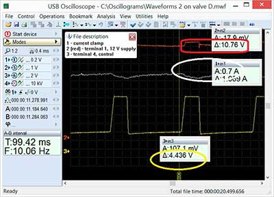
To gather more data, we used three channels from the oscilloscope as shown in Figure 3, waveform #2.
Channel 1: Current clamp.
Channel 2: Supply voltage on terminal 1 of the Transmission valve block.
Channel 3: Control voltage on terminal 4 of the Transmission valve block.
As can be seen in the oscilloscope capture, the supply voltage does not fall below 10.8V, and the solenoid current consumption is normal at approximately 1A. There are no current spikes present in the waveform, which indicates the absence of mechanical seizing or “stickiness” of solenoid “D”. Based on these observations, there are no external factors that could overload the pressure control solenoid driver. The load is electrically sound, but the driver is unable to provide normal current through the solenoid “D” and is incapable of pulling the circuit below 4.4V.
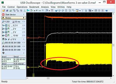
By using a long time base or time compressing the waveform, the failure becomes clearly visible as shown in Figure 4.
This type of failure could be a defective output transistor driver in the PCM or a poor ground for the driver. In order to determine if it is the driver or the ground, we can check the PCM grounds with an oscilloscope. One way to do this is to connect the four channels of an oscilloscope as follows:
Channel 1: Control voltage of Solenoid “D”.
Channel 2: Ground 1.
Channel 3: Ground 2.
Channel 4: Ground 3.
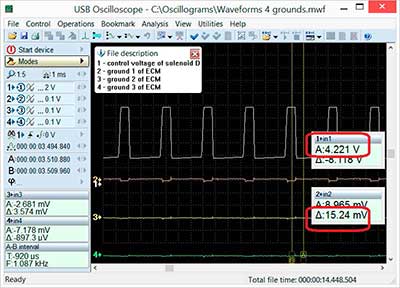 On the waveforms in Figure 5, we can see that the solenoid circuit does affect one of the grounds. The affect, however, is infinitesimal at only 15 mV and will have no discernible effect on the operation of the driver. Based on these measurements we can conclude that the reason for the 2716 DTC is inside the PCM.
In Toyota’s TSB (TC015-07), it was confirmed that the PCM in our vehicle, 89661-02S13, is one of the affected control units. The TSB says to replace the PCM. Replacing the PCM does involve considerable expense. It is also a pity to change an otherwise perfectly operational PCM due to one minor defect. The question then becomes: Is it possible to repair the PCM? To answer the question, the control unit was disassembled and the driver that controls the operation of solenoid “D” was located.
Repair
Examination of the PCM board revealed a factory defect. The problem was a cold solder joint of two pins of the driver. Since the repair did not involve modifying the circuitry or replacing components, the chip was resoldered.

Considerable testing after the repair verified that the P2716 DTC did not return. The final confirmation test was done using an oscilloscope. The waveform seen in Figure 6 was recorded on terminal 4 of the transmission solenoid connector. In this capture it can be seen that the solenoid driver is capable of pulling the voltage down to about 214 mV, which is the normal voltage seen from this type of transistor driver.
Using an oscilloscope, it is possible to solve difficult and complex problem diagnoses. The cost to repair failures can also be reduced. The satisfaction that comes from being able to solve and repair complex technical failures cannot be discounted either.