I have a great tip you can add to your diagnostic tool kit when using the VCMI module that comes with the Autel MSUltra and MS919 scan tools.
The VCMI has many features, such as a powerful 4-channel scope, a graphing multimeter, a waveform generator, and a Bus Inspection tool.
These tools can be accessed by tapping on the “Measurement” icon on the main menu item.
Today, we will be speaking about the Waveform Generator. This is an excellent feature to use to diagnose sensors and actuators.
Launch the waveform generator. The DC Voltage Signal screen will display. Here, we can apply DC voltage signals to test the components.
Autel offers a dynamic help function on this system. Tap the Help icon, and the relevant section of the manual will display.
Let’s first apply a known voltage wave pattern to a circuit to simulate a signal or to actuate a component.
The first option in the toolbar is DC Voltage. This mode generates a DC voltage signal. One application of this feature is thermistors and thermocouples testing. Other applications include voltage testing of an engine coolant sensor to confirm the operation of cooling fans and electric water pumps. Applying different voltages to an engine coolant sensor assures the operation of cooling fans and electric water pumps. The VCMI’s Wave Generator can apply as little as .1 or as much as 12 volts.
The next signal in the menu is for square waves. Square waves are how many Hall-effect sensors communicate. This feature can simulate signals from crankshaft position sensors and even wheel speed sensors.
The next item is for square waves X+Y. This function is mainly used to simulate the missing tooth signals of Hall-type crankshafts and camshafts. The X value represents the normal tooth signal, and the Y represents the absent tooth signal. The default setting is 58+2, which can be adjusted as needed.
The square wave x+y feature can help simulate a crankshaft position signal. This is a helpful test in a crank/ no start condition to determine if the sensor is defective.
The next item in the toolbar is for Triangle waveforms. Displayed here is a symmetrical triangular waveform. The technician can modify this waveform’s amplitude and frequency. Triangle waveforms are used for inductive sensors that track the position of some camshaft and distributor position sensors.
The Actuator drive test function can be used to power electric motors and solenoids with a pulse-width modulated signal. The frequency and duty cycle can be controlled from the scan tool interface. This can help you diagnose transmission solenoids, oil control valves and fuel injectors.
The arbitrary waveform setting can reload saved waveform and parameter settings like hertz and duty cycle.
Let’s try some of these new tools out on a vehicle.
The VCMI module has 3-ways you can connect it to your tablet. A hardwired USB cable, Bluetooth, or Wi-Fi.
The first need to test the crankshaft position sensor. The vehicle came in with a crank/no-start condition. Looking at the service information, the ECM needs a crankshaft position signal to activate the ignition system and fuel injectors. Without the signal, the vehicle will crank but not start.
Using the breakout leads included with the kit, we can connect to the sensor. The leads will connect to the black common/ground and red voltage connectors on the VCMI.
Next, we will select the Square Wave x+y in the toolbar.
Consult vehicle service information for crankshaft position sensor data, like signal voltage levels. Some service information sources will include a “known good” waveform.
With this information, we can generate a crankshaft position sensor signal the ECM might recognize.
If we adjust the frequency, it is like changing the engine speed. The X value represents the normal tooth signal, and the Y represents the missing tooth signal or areas of the sensor ring that might have teeth grouped together or omitted.
Let’s try to crank the car. Without the signal generator, the car just cranks. We are not seeing any activity from our test lights on the coils or fuel injectors. When we tap the green play button at the top of the screen, the signal is generated. Now, we can see the ignition coils and fuel injectors are firing.
Let’s say after replacing the crankshaft position sensor, the vehicle still does not start.
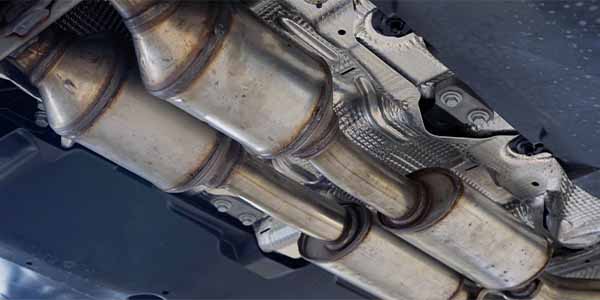
We can continue with the Waveform generator to test the next possible culprit, the oil pressure sensor. The oil pressure sensor on this engine is a pressure transducer. It has three wires. Ground, supply voltage and signal. We will again use the breakout leads included in the kit. We will connect the VCMI to the ground and signal wire like this.
The pressure transducer receives five volts through the supply voltage wire. As pressure increases, the voltage on the signal wire will increase.
Using the DC Voltage setting, we can simulate the oil pressure sensor. We will start at one volt to see if the engine will start. We can increase the voltage until the engine starts.
With these two easy checks, I can confirm what parts will cure the no-start condition. This way, when I go to order the part, I know it will fix the vehicle.
The Autel VCMI has other features, such as a powerful 4-channel scope, a graphing multimeter. Great for intermittent fault testing and a J2534 programmer-supporting protocols like DOIP and CAN FD. It even has a data bus tool to diagnose CAN and other vehicle networks in the OBDII connector.
As you can see, the Autel VCMI has quite a bit to offer. To find out more about this tool or any of Autel’s family of tools, visit www.autel.com.
Thanks for watching.
This video is sponsored by Autel.