The passive wheel speed sensor has been around a long time. It works quite differently than the active speed sensors that are found on most cars today. The passive speed sensor creates its own AC signal that changes frequency with wheel speed. This signal is only present while the wheel is turning at a rate fast enough to create the AC signal.
Vehicles equipped with passive wheel speed sensors generally do not read at or below 2 mph coming from a dead stop. During a wheel spin condition, or under a condition where one wheel is turning slower than the other three wheels, the system will reduce the hydraulic brake pressure (under braking conditions) to allow that wheel to regain its traction with the road surface.
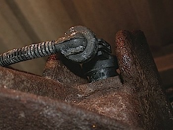
The signal can be affected by a number of different problems. From a weak sensor, damaged tone ring, debris, rust, wiring issues, or the gap between the sensor and the tone wheel. (One of the most common problems I’ve found is when someone replaces the sensor, but does not push it in all the way causing a fault code for that sensor.) Any variation in the preset values not reaching the ABS control will set a code for that particular sensor (in most cases). Some of the draw backs of the passive-type wheel speed sensor are its inability to operate at very low speeds or in reverse. This is one of the many reasons why most manufactures have gone to active wheel speed sensor systems.
Distinguishing which Sensor Type
Determining which type of speed sensor is on the car you’re working on can be done several different ways. Obviously, checking the manufacturer’s specs is a good way, or with your scanner. Although, looking at the sensor itself won’t give you any clues. They are both two-wire sensors and they both look basically the same. The main difference would be the resistance readings. The typical reading for a passive wheel speed sensor is between 1,000 and 2,500 ohms, while the active speed sensor is 5 to 6 Mega Ohms or more. (I wouldn’t rely on this as the ultimate answer, just in case there is a problem with the sensor itself and what you’re seeing is a false reading.)
BIAS Voltage
Some vehicles will send a DC voltage to the sensor through the ground wire of the sensor. The signal will travel up the leads just as the generated AC signal does. This allows the sensor to be tested by the ABS system without the vehicle moving. This can set a code shortly after the key is turned on if there is a problem with the wiring, connection or the sensor itself. This DC signal is not generated by the sensor, but by the controller and is only used as a way to verify the sensor is there, not the actual ability of the speed sensor to create the AC signal. That’s entirely up to the rotation of the wheel.
High resistance or an open circuit can be immediately detected by the BIAS voltage. Anytime the BIAS (DC) voltage is not received back at the ABS controller, the controller will assume the sensor is not functioning. To measure this BIAS voltage, a lab scope is going to be your best choice. Have the ground lead of the scope on a good battery ground, and the positive lead connected to the signal wire at the sensor. Without the wheel spinning, you can observe the DC voltage being supplied to the circuit.
Testing the Sensor
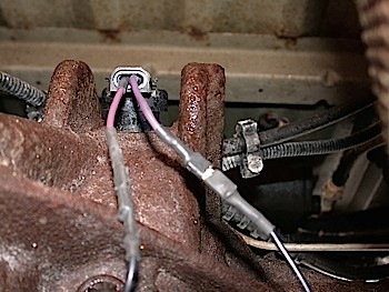
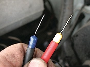
If the signal is viewed on a scope, the voltage will rise above the zero volt line when the key is turned on. A typical BIAS voltage is about 2.5 volts (some manufacturers use a slightly higher voltage). You might be able to read this with your DVOM, but I prefer using a scope myself. I like using a T pin (one of my wife’s quilting pins) tucked into the connector as my test point. Never stab directly into the sealed wiring of the sensor leads as this can cause problems down the road when water, salts and other debris start to seep into the opening you just created.
On some vehicles, when the sensor is unplugged, the BIAS voltage is turned off by the ABS controller. So if you are trying to read the voltage, you’ll have to do it without disconnecting the sensor. Basically, any disturbance in the two wires from the controller to the sensor can be detected by the controller as a problem and can cause the loss of the BIAS voltage. The controller will “self-save” itself from any damage this way. In these cases, if you do not see the BIAS voltage at the sensor, it’s a good time to start tracing for a bad connection or broken lead.
Practice makes Perfect
With a little practice, you can diagnose these sensors quickly and efficiently in no time at all. Understanding how they work and how to properly test these sensors will make your job easier and more efficient. A good method of increasing your skills is to practice hooking up the scope or scanner to a speed sensor on those slow days at the shop. That way when the need arises, you’ll be the sharpest tool in the diagnostic tool box.