SNAP-ON DIAGNOSTICS TECHNICAL REFERENCE
By Damien Coleman, Snap-on Diagnostic Software Specialist
Motor vehicles have become increasingly more complex over the last two decades to meet the ever-tightening emissions regulations and increased fuel economy requirements, as well as passenger comfort and safety.
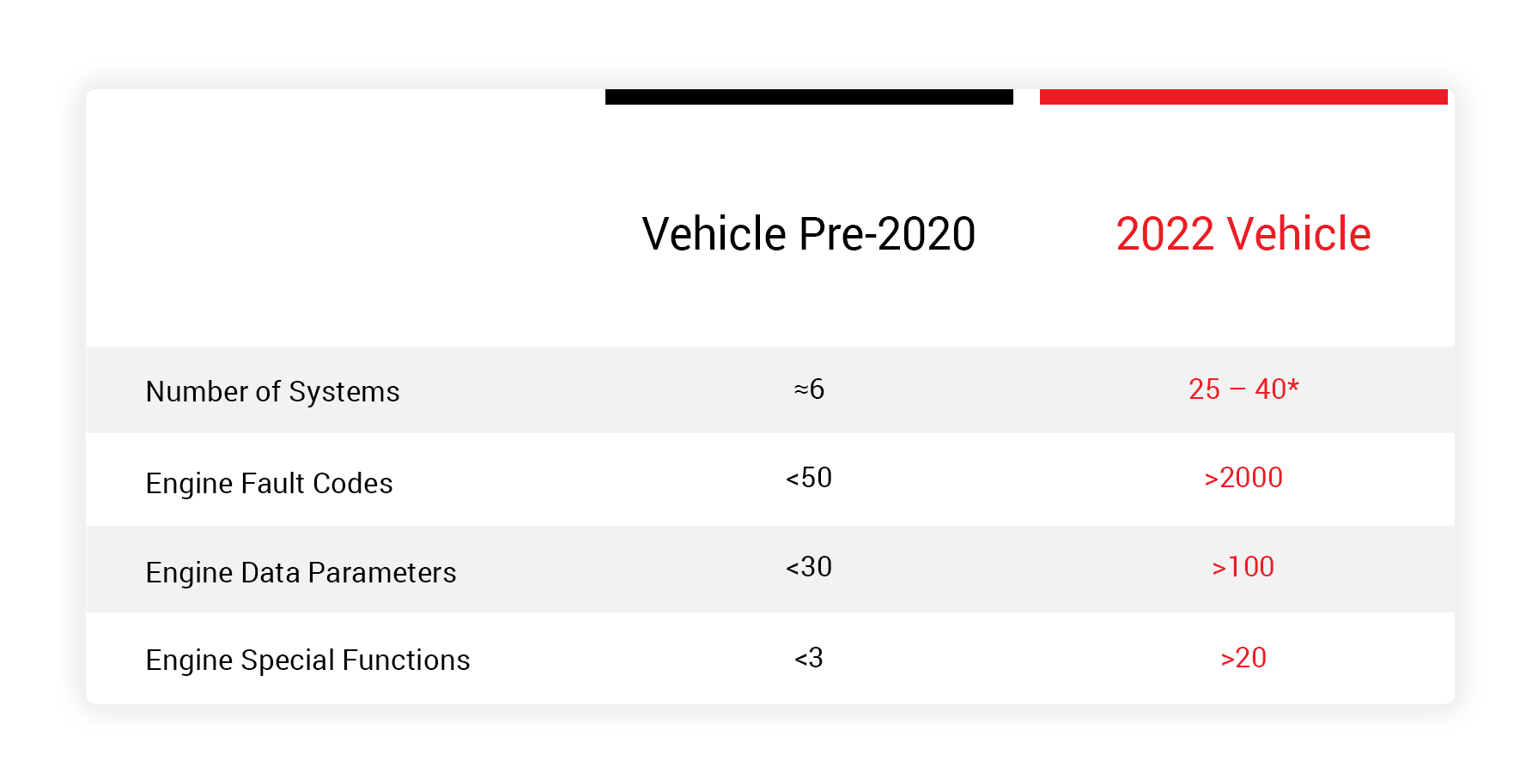
This added complexity means technicians are flooded with additional data when diagnosing faults on vehicles. Below is a table outlining the difference between a modern vehicle and a vehicle from 20 years ago. This is only a high-level example to illustrate the differences:
Fault Codes
However, with all the additional fault codes and data parameters, the technician is given more information, which can help quickly and accurately diagnose any faults. For most fault codes there are a number of possible sub-codes. These sub-codes give the technician an indication of the condition which caused the fault code to be stored. Examples of this for turbocharger system fault codes are:
- turbocharger boost pressure – negative deviation (under-boost)
- turbocharger boost pressure – positive deviation (over-boost)
- turbocharger boost control circuit – voltage high
- turbocharger boost control circuit – voltage low
If a fault code won’t clear with the ignition on and the engine off or the fault returns immediately once the ignition is switched on, the issue is most likely not mechanical in nature. An over-boost or under-boost fault will only be set after a test drive.
Live Data
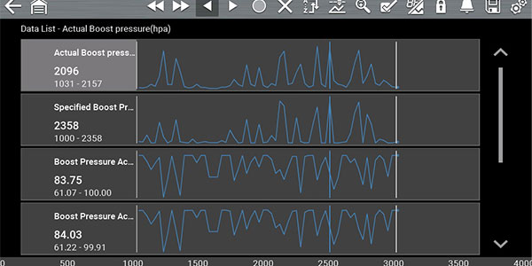
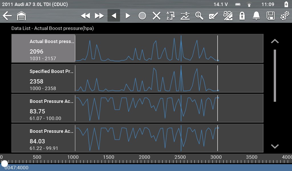
Many data lists will have two parameters for certain components or sub-systems. The screenshot below shows actual and specific boost pressure. Comparing these data parameters is important to ensure the vehicle is operating under the conditions expected by the management system. There will be a certain amount of latency between these paramaeters, but the returned values should be similar.
Command and feedback is also evident here with the data parameters for boost pressure actuator, activation value (percent) and boost pressure actuator, feedback value (percent). This shows the control from the engine control module acting on the turbocharger vane position actuator and the feedback from the turbocharger position sensor, which is inferred to as a percentage.
Special Functions
Many engine components must be adapted to the vehicle when replaced. Previously, components like turbocharger actuators were “plug and play.” Now these components must be matched to the system. This is a way of setting the base position for the actuator and position sensor and is used to detect possible faults or incorrect operation.
Oscilloscope Testing
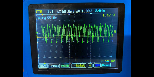
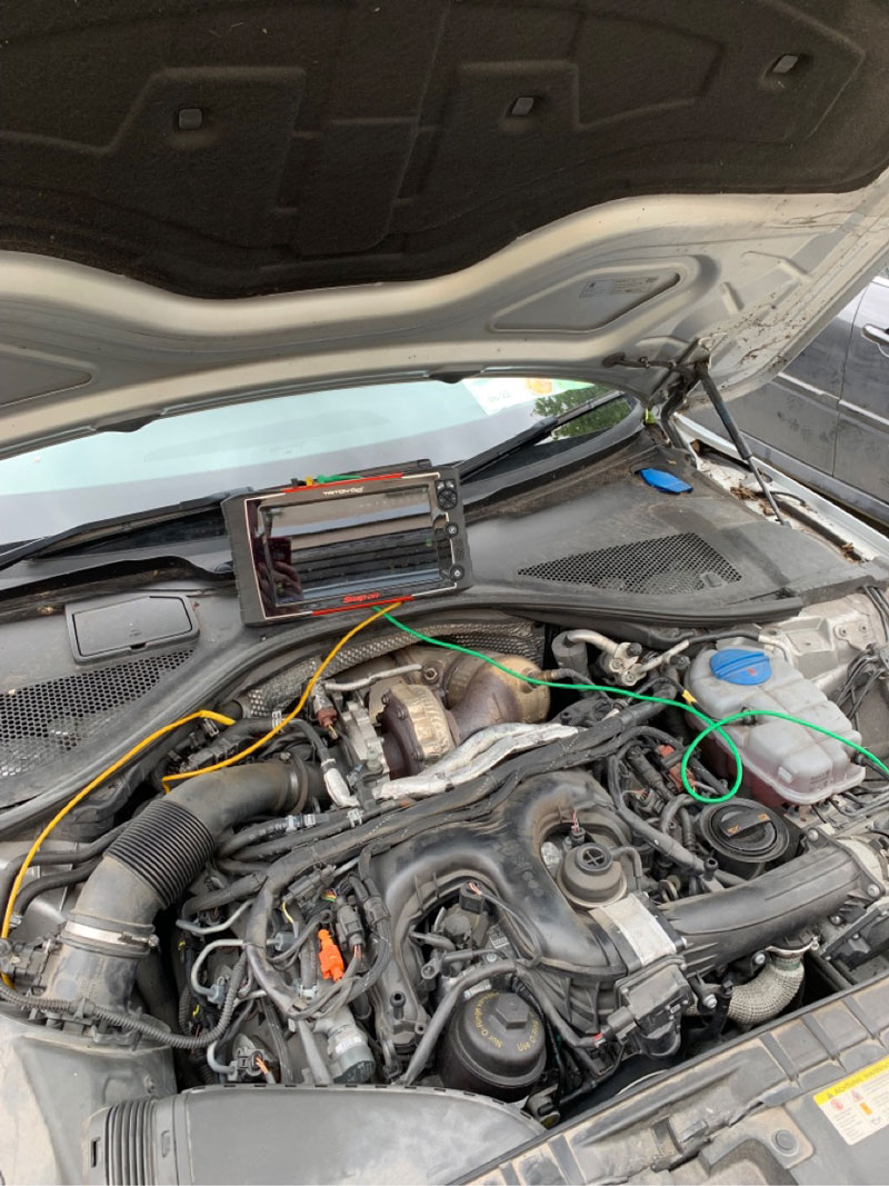
Another option to investigate the operation of a system is to use an oscilloscope. A scope provides a graphical representation of voltage over a particular time duration. The waveform below shows the output from the boost pressure sensor and the feedback from the turbocharger vane position sensor under wide open throttle operation on a road test.
Not only is the scope good for diagnosing faults and validating repairs, but it can also be used to give the technician an in-depth understanding of the operation of a complicated system.
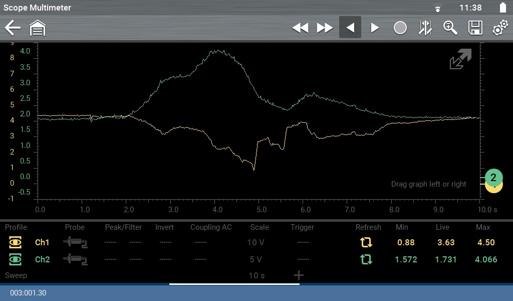
Yellow Channel – Turbocharger Vane Position Sensor
Green Channel – Boost Pressure Sensor
For more information, click HERE.