Customers may comment about various driveability and/or engine operating concerns including: hard start, erratic idle, rough running, engine overheating, low and/or leaking coolant and/or Service Engine Soon lamp illuminated on 1991-2001 Saturn S-Series vehicles. This condition may be caused by a cracked engine coolant temperature sensor. You’ll need to replace the engine coolant temperature sensor, inspect and, if necessary, replace the sensor harness connector.
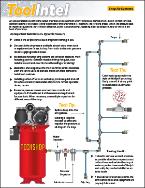
Procedure: 1. Disconnect the engine coolant temperature (ECT) sensor electrical connector and inspect sensor and connector terminals for corrosion and/or evidence of engine coolant. See Figure 1.
• If the terminals are corroded or if there is evidence of engine coolant, proceed to step 4.
• If the terminals are not corroded and there is no evidence of engine coolant, reconnect the electrical connector and continue to the next step.
Caution: To avoid the danger of being burned, do not remove the cap while the engine, radiator and surge tank are still hot. Scalding fluid and steam can be blown out under pressure.
2. Perform one or both of the following checks to determine whether the ECT sensor is providing the correct temperature indication.
• If the engine is at ambient temperature (the vehicle has been sitting overnight or not started for several hours), use a scan tool to compare the inlet air temperature (IAT) to the ECT. These two readings should be within 2° C (4° F) of each other.
• If the engine is at operating temperature, install a thermometer in the coolant recovery reservoir. With the engine running and A/C off, use a scan tool to compare the ECT sensor reading to the thermometer reading. These two readings should be within 8° C (15° F) of each other.
• If the ECT sensor reading does not pass either of the above tests, continue with the next step.
• If the ECT sensor reading passes both of the tests above, refer to the appropriate symptom diagnostic chart in the Engine/Emissions Controls section of applicable engine service manual.
3. Turn off the ignition.
4. Remove the coolant surge tank cap.
Caution: Do not remove the cap or open the cooling system drains from a hot system. Allow the system to cool first.
5. Drain at least 1.9L (2 qt.) of engine coolant from the cooling system by opening the radiator drain valve or removing the engine drain plug. Collect the engine coolant in a container.
6. Disconnect the ECT sensor electrical connector.
7. Remove the ECT sensor from the cylinder head.
8. Obtain the replacement ECT sensor (P/N 21025106).
9. Use the appropriate tap to clean the sensor mounting hole of any thread sealant residue.
10. Install the ECT sensor in the cylinder head.
Torque: ECT Sensor: 8 Nm (71 in.-lbs.)
11. Inspect the harness connector terminals for corrosion and/or evidence of engine coolant. If the harness connector terminals are corroded or there is evidence of engine coolant, the harness connector must be replaced with a new connector (P/N 12117087-includes: connector, terminals, wires and splice sleeves).
12. Connect the ECT sensor connector.
13. Transfer the engine coolant drained in step 5 into a coolant surge tank. If necessary, fill the coolant surge tank to the FULL COLD range with 50/50 solution of the correct type of antifreeze and clean water.
14. Start the engine and check for leaks.
15. Run the engine until the upper radiator hose is hot, then add more coolant if needed to bring the level to the FULL COLD level (1991-early 1997) or within the Min./Max. cold range (late l997-2001).
16. Install the coolant surge tank cap.
Technical service bulletin courtesy of Mitchell 1.
For additional information, visit www.mitchell1.com.