With fuel prices rising, the need for accurate air/fuel mixture monitoring is more important than ever. The engine computer needs to know what the fuel mixture is with a high degree of precision so it can optimize fuel economy as well as emissions. If the information received by the powertrain control module (PCM) from its sensors is not accurate, it may command too much fuel or not enough. A rich mixture wastes fuel, while a lean mixture may misfire and waste power (while also causing a big increase in hydrocarbon emissions).
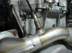
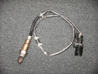
Many late-model imports such as Honda, Toyota, Volkswagen and others use “Air/Fuel” (A/F) sensors rather than conventional oxygen (O2) sensors to monitor the exhaust gases coming out of the engine. What’s the difference? An air/fuel sensor can read a much wider and leaner range of fuel mixtures than a conventional O2 sensor. That’s why they’re also called “wideband” O2 sensors.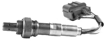
Another difference is that A/F sensors don’t produce a voltage signal that suddenly changes on either side of Lambda when the air/fuel goes rich or lean. A conventional O2 sensor will produce either a rich reading (0.8 volts) or a lean reading (0.2 volts) when the fuel mixture changes. An A/F sensor, by comparison, produces a changing current signal that varies in direct proportion to the amount of unburned oxygen in the exhaust.
On Toyotas, the PCM sends a 3.0-volt reference voltage signal to the A/F sensor. A detection circuit inside the PCM then monitors changes in the current flow, and generates an output voltage signal that is proportional to the air/fuel mixture. At Lambda, when the air/fuel mixture is 14.7 to 1 (stochiometric), the current flow through the sensor is zero.
If the air/fuel mixture goes rich, the current increases in one direction (negative). If the air/fuel mixture goes lean, the current increases in the opposite direction (positive). From this, the PCM generates a voltage signal that varies as the air/fuel mixture changes. This signal may range from a low of around 2 volts (very rich) up to nearly 4 volts (very lean). At Lambda, the voltage signal generated by the PCM will be 3.3 volts.
One of the key points to keep in mind about the differences between A/F sensors and conventional O2 sensors is that the voltage signal goes up (not down) when the fuel mixture is lean. Another is that the voltage signal is coming from the PCM, not the sensor itself, so you can’t read an A/F sensor’s output voltage directly with a digital storage oscilloscope (DSO) like you can with a conventional O2 sensor.
Another point that can trip up an unwary technician is that the A/F value displayed on a scan tool can be misleading. Many scan tools with “generic” OBD II software automatically convert the PCM’s A/F sensor voltage output to a more familiar 0 to 1 volt scale like that of a conventional O2 sensor. If you are not aware of this fact, and wonder why the voltage reading for the A/F sensor PID seems unresponsive, or does not change as much as you would expect when you create a lean or rich fuel condition, you may wrongly conclude that the A/F sensor is bad.
The most accurate way to test A/F sensors is with a factory scan tool that displays the PCM’s actual voltage reading for the A/F sensor, or an aftermarket scan tool that can do the same.
A/F SENSOR PROBLEMS
A/F sensors fall prey to the same ailments as ordinary O2 sensors. A contaminated sensor will not produce an accurate signal or generate an accurate air/fuel mixture reading. Sensors can be contaminated by engine coolant from internal coolant leaks (leaky head gasket or cracks in the cylinder head), or by phosphorus if the engine is burning oil. The underlying cause here may be worn valve guides and valve guide seals, and/or worn piston rings or cylinders. Other sources of contamination include RTV sealers that contain high levels of silicone, or certain gasoline additives.
If an A/F sensor is lightly contaminated, it may be lazy and take longer to respond to sudden changes in the air/fuel mixture. If the sensor is heavily contaminated, it may not respond to changes at all.
Compression leaks or misfires that allow unburned oxygen to enter the exhaust, and exhaust manifold air leaks, can also mislead the sensor.
A/F HEATER CIRCUIT
Problems can also occur in the A/F sensor heater circuit. A/F sensors require a higher operating temperature (1,200° F compared to about 650 to 750° F for a conventional O2 sensor). If the heating element is bad, or there is a wiring connector problem in the heater circuit, the sensor may not reach the proper operating temperature. This will usually (but not always) set a heater circuit fault code. If you find such a code, always check the wiring circuit first before condemning the sensor itself. Refer to the wiring circuitry for the sensor to check the supply voltage and ground. Most A/F sensors have five wires (though some have four or six).
On V6 and V8 engines where two A/F sensors are used (one for each bank), the heater circuit is usually routed through a relay. The heater circuit carries up to 8 amps of current, with the current being controlled by the PCM with a duty ratio pulse width modulator circuit. When a cold engine is first started, the duty ratio is high to provide maximum current to the heater element so the sensor will warm up quickly. Once the sensor reaches operating temperature, the duty ratio is cut back to reduce current to the heater circuit. The PCM monitors the operation of the heater circuit, and will set a P0125 code if a fault occurs. It will also kill power to the heater circuit.
BAD A/F SENSOR OR SOMETHING ELSE?
An engine that’s running rich may not set any fault codes, but a lean fuel condition will often set a P0171 or P0174 lean code. The question is, where should you start your diagnosis? You may suspect a faulty A/F sensor, but it might be something else such as a contaminated mass airflow sensor or even a faulty coolant sensor.
Lean codes are set when the Long Term Fuel Trim (LTFT) reads overly lean. Connect a scan tool and verify the engine has a lean fuel condition by looking at the LTFT value. Normal range is typically plus or minus five. If the reading is 8 to 10 or higher, the PCM is adding extra fuel to compensate for a lean air/fuel mixture reading. This may be due to an intake manifold vacuum leak, a loose vacuum hose or an EGR valve that is not closing.
If no vacuum or EGR leaks are found, check fuel pressure to see if it is within specifications. Low fuel pressure due to a weak fuel pump, plugged fuel filter or leaky fuel pressure regulator could be causing a lean fuel condition. Dirty fuel injectors are another possibility.
If the fuel system checks out okay, check the Calculated Load Value PID on your scan tool. Look for a change in the indicated airflow value when you rev the engine. If the sensor element in the MAF sensor is dirty, it may be underreporting airflow to the PCM, causing a lean fuel condition. Cleaning the sensor element with some aerosol MAF sensor cleaner may be all that’s needed to restore proper operation.
If the MAF sensor appears to be reading normally, check the engine coolant sensor to make sure it is reading within range. Compare the coolant sensor reading with the intake air temperature sensor reading on your scan tool when the engine is cold. Both readings should be the same. A difference of more than a few degrees indicates a problem.
If everything else checks out, the problem may be contaminated or biased A/F sensor(s) that are not reading accurately. On Toyota applications, the factory scan tool has an “Active Test A/F Controls” option. This is found on the menu under Diagnosis, Enhanced OBD II, Active Test, A/F Control. The test varies the fuel mixture while the engine is idling to test the response of the A/F sensors.
On aftermarket scan tools that lack this test function, you can use the following procedure to test the A/F sensors:
• Idle the engine for 30 seconds, then raise the engine speed to 2,500 rpm and hold steady. Watch the voltage reading for the sensor. If the sensor is working normally, you should see a reading of around 0.66 volts (if the signal is converted to OBD II generic), or 3.1 to 3.5 volts if you are reading the voltage signal generated by the PCM for the A/F sensor(s).
• Next, rev the engine to 4,000 rpm and release the throttle so the engine returns quickly to idle. This will cause a momentary leaning of the fuel mixture as the fuel cuts off during engine decel. The air/fuel sensors should respond by showing a momentary jump in voltage to 3.8 volts (direct reading) or 0.76 volts (OBD II generic).
If the voltage output remains flat at 3.3 volts (direct reading) or 0.66 volts (generic OBD II reading), and the reading does not change with engine speed or throttle position, the air/fuel sensor may have an internal open circuit, or its heater circuit may be open.
The resistance of the A/F heater circuit can be checked at the wiring connector (between terminals HT and +B on a Toyota). At room temperature, the resistance spec for a Toyota is 0.8 to 1.4 ohms.
The A/F sensor heater relay should also be checked to make sure it is working. On a Toyota, unplug the relay and measure the resistance between terminals 3 and 5. It should be 10K ohms or higher.
A/F FAULT CODES
Generic OBD II codes that indicate a fault in the A/F sensor heater circuit include: P0036, P0037, P0038, P0042, P0043, P0044, P0050, P0051, P0052, P0056, P0057, P0058, P0062, P0063 and P0064.
Codes that indicate a possible fault in the A/F sensor itself include any code from P0130 to P0167. There may be additional OEM “enhanced “P1” codes that will vary depending on the year, make and model of the vehicle.
On Hondas, for example, common A/F sensor codes include P1166 and P1167. Keep in mind the fault may be in the sensor or the sensor wiring.
A/F sensor codes identify the sensor by its location, such as sensor 1 or 2, bank 1 or 2. Sensor 1 represents the “upstream” A/F sensors in the exhaust manifold. Sensor 2 is “downstream” O2 sensors behind the catalytic converter. Sensor 2 is conventional O2 sensors, not wideband A/F sensors. Bank 1 is the side that includes cylinder number one in the engine’s firing order. Bank two is the other side. If you don’t know which cylinder is number one, look it up. Don’t guess, otherwise you might replace the wrong sensor.
“False” codes can sometimes be a problem with A/F sensors just like with any other type of sensor. On some 2004 Toyota Camrys, a code P2238 may be set indicating a fault with the sensor 1 bank 1 A/F sensor. Toyota bulletin EG034-04 says the fix may require replacing the A/F sensor and reflashing the PCM with a revised calibration that makes it less sensitive to setting this code.