There was a time when our brake lathes never stopped, humming their metallic tune almost all day long. If rotors or drums could be turned, that’s what we did, but it’s a rare occurrence today. We almost always replace them. Most shops still have their lathe because it’s valuable equipment, and while it’s silent most of the time, when you need it, you need it.
Resurfacing drums or rotors is a machining process with its own specific guidelines to follow. So, the next time you need to blow the dust off the machine, here’s a refresher on some brake lathe basics to make sure your lathe is humming in the right key. If you’re new to the process, that’s more than just a bad joke. You can always tell when your cut is going well by the sound. If it changes, so is the quality of the cut.
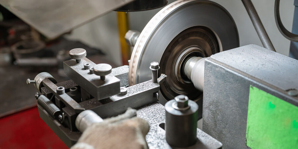
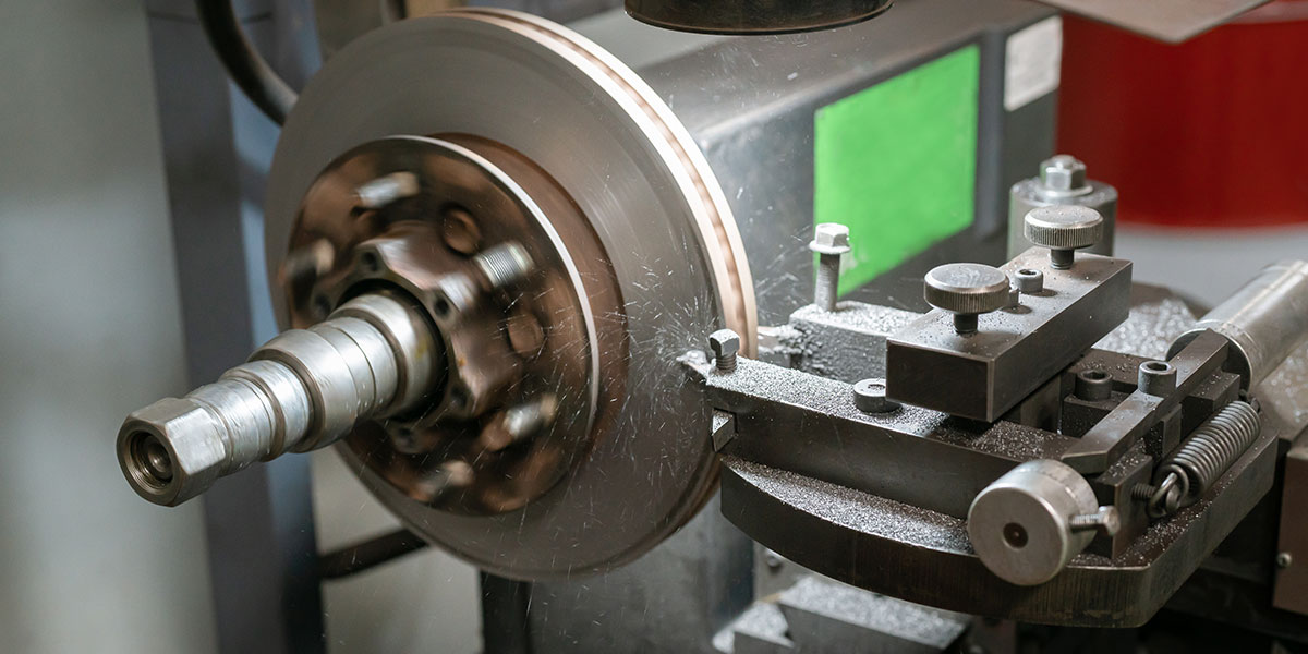
The basic operation of a lathe consists of mounting a drum or rotor onto a spindle. The spindle shaft is turned by a motor, which rotates the mounted component. When a cutting bit contacts the turning component, metal is removed.
There are two different feeds on a brake lathe: spindle feed (the distance the spindle moves per revolution) and cross feed (the distance that the cutting tool moves per revolution of the spindle). Spindle feed is used for brake drums, and when engaged, the spindle moves to the left, which moves the surface of the drum across the fixed cutting tool. Spindle feed rate is adjustable on most lathes.
Cross feed is used when turning brake rotors. In this case, the rotor is turning but the spindle remains fixed, and cross feed pulls the cutting bits across the rotor. Cross feed speed has a fine and course adjustment. The key to successful resurfacing is based upon the combination of spindle rotation speed, spindle feed or cross feed speed, correct component mounting and vibration elimination.
Mounting hubbed drums or rotors is accomplished by using tapered cone adapters. Choose the sizes that are closest to contacting the middle of the bearing races.
Mounting hubless drums utilizes hubless adapters, along with a spring and cone to center the drum. Hubless rotors also utilize a cone and spring to center the rotor, but a different style of adapters. Be sure all mounting surfaces are free of rust or debris. Use spacers as necessary to reach the arbor nut, and always be sure to use the self-aligning spacer next to the nut to prevent diagonal thrust on the adapters.
When turning a drum, first install the drum silencer band, making sure it is wrapped up to the right-hand edge. Position the boring bar so it is close to the drum and tighten it. Turn the drum by hand to make sure everything is clear, then start the lathe. Using the cross-feed handwheel, bring the cutting bit toward the drum until it just contacts it and makes an initial scratch cut.
Back the bit away from the drum, turn the lathe off, then loosen the arbor nut and rotate the drum 180 degrees and retighten the nut. Start the lathe once again, rotate the spindle feed handwheel a ½ turn, the bring the cutting bit toward the drum once again to make another scratch cut. Turn the lathe off and look at the scratch cuts. If they are on opposite sides of the drum, you most likely have dirt or a burr on a mounting surface. If they are side-by side, the drum is properly mounted and you can proceed with resurfacing.
As a general rule, rough cuts for a drum should be no deeper than 0.020”, and finish cuts no shallower than 0.004” (adjusted using the cross-feed handwheel). The spindle feed for cutting a drum should be 0.006” to 0.020” (adjusted with the spindle feed dial while the lathe is running).
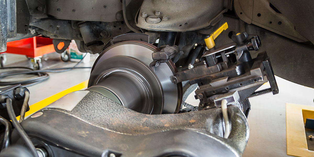
When turning a rotor, the twin cutter is used to cut both sides of the rotor at one time. Install the rotor silencer band, then center the twin cutter around the rotor. You can use the spindle handwheel to help position the rotor but be sure to lock the spindle position afterward. Here’s a step many people miss: Adjust the spindle speed to match the rotor size.
On the most common lathes, this is done by moving the spindle drive belt between grooves. The outer pully groove is for most passenger car and light truck rotors; the inner grooves for larger and solid rotors. The important point is, you are changing the speed based on the size of rotor, slowing it down for larger rotors.
As with the brake drum, rotate the rotor by hand to make sure everything is clear, then start the lathe. Cutting bits are adjusted by using the knurled knobs. Use the cross-feed handwheel to position the bits midway on the rotor surface and make a scratch cut. These are almost always an incomplete circle, but it can be caused by rotor runout or by incorrect mounting. Similar to the procedure with a drum, turn the lathe off, loosen the arbor nut and rotate the rotor 180 degrees.
Make a second scratch cut. If they are side by side, the runout is caused by the rotor, but if they are opposite each other, there is most likely a burr, rust or debris on the mounting surfaces. Once you have confirmed the rotor is mounted correctly, you can proceed with resurfacing.
Rough cuts should be taken with the cross feed speed lever in the fast position; finish cuts in slow. Rough cuts should be 0.006” to 0.010” per side, and finish cuts should be 0.004” to 0.006”. Cuts shallower than 0.004 tend to reduce the life of the cutting bit, because the heat generated isn’t transferred to the rotor. Enjoy the music! TS