Fire Suppression System The Ford Crown Vic Police Interceptor, or CVPI, has been around since 1992. The current crop of CVPIs do not differ much mechanically from their predecessors, but on the undercar electronics, the vehicle has advanced dramatically in the past 10 years.
In 2006, Ford equipped the CVPI with a fire suppression system. The activation system is controlled by the module that is on the Controller Area Network (CAN) BUS and uses data from the various sensors on the vehicle, including wheel speed sensors. This system even has its own diagnostic codes.
The fire suppression module is non-repairable. The fire suppression module uses hardwired circuitry, internal sensors and internal back-up power supply. The fire suppression system can be diagnosed with a diagnostic tool through the ISO network. Communication using the CAN circuits transmits and receives data between the fire suppression module, the PCM, and the ABS module.
 It is a good idea to de-power the system before any work is performed. Refilling these systems can be very expensive. The system can even activate if the key is not in the vehicle, the goal of the deactivation procedure is to deplete the back up power supply before the vehicle is serviced or lifted.
To deplete the backup power supply, disconnect the battery and wait at least one minute. Be sure to disconnect the auxiliary batteries and power supplies (if equipped). Failure to follow these instructions may result in personal injury.
Always wear safety glasses when repairing a fire suppression system vehicle and when handling a fire suppressor. This will reduce the risk of injury in the event of an accidental deployment.
To reduce the risk of accidental deployment, never probe the connectors on the fire suppressors. Failure to follow this instruction may result in personal injury.
To reduce the risk of accidental deployment, do not use any memory saver devices. Failure to follow this instruction may result in personal injury.
Depowering Procedure
NOTE: The fire suppression system indicator lamp illuminates when the fire suppression module (FSM) fuse is removed and the ignition switch is ON. This is normal operation and does not indicate a fire suppression system fault.
1. Turn all vehicle accessories OFF.
2. Turn the ignition lock cylinder to the OFF position.
3. Remove the central junction box (CJB) fuse 33 (10A).
4. Turn the ignition lock cylinder to the ON position and visually monitor the fire suppression system indicator for at least 30 seconds. The fire suppression system indicator will remain lit continuously (no flashing) if the correct FSM fuse has been removed. If the fire suppression system indicator does not remain lit continuously, remove the correct FSM fuse before proceeding to the next step.
5. Turn the ignition lock cylinder to the OFF position.
NOTE: If the battery voltage is required for diagnostic procedures, the battery must be connected without installing the FSM fuse.
6. Disconnect the battery and wait at least one minute.
Repowering Procedure
1. Install the CJB fuse 33 (10A) to the CJB and close the cover.
NOTE: This step is not required if the battery was connected after depowering procedure.
2. Connect the battery.
3. Prove out the fire suppression system as follows:
• Turn the ignition lock cylinder from the OFF to the ON position and visually monitor the fire suppression system indicator. The fire suppression system indicator will light continuously for approximately six seconds and then turn off. If a fire suppression system fault is present, the fire suppression system indicator will fail to light, remain lit continuously or flash.
• The flashing might not occur until approximately 30 seconds after the ignition lock cylinder has been turned from the OFF to the ON position. This is the time required for the fire suppression module to complete the testing of the fire suppression system. If this occurs, the fire suppression system fault discovered must be diagnosed and repaired.
Clear all continuous DTCs from the fire suppression module using a diagnostic tool.
Pads, Rotors and Wheel Bearings
Do not skimp on the quality of rotors, pads and calipers. To an officer, a pulsation, noise or anything out of the ordinary is more than a comeback, it usually means that the vehicle will be pulled out of service and will cost the taxpayer money. Also, the CVPI is unique in its performance requirements, and the aftermarket has pads and rotors that can meet these requirements.
Before ordering pads, take a look at the pistons in the rear caliper. Some models are equipped with steel pistons or phenolic pistons. This occurs on some pre 2003 models, but can change due to what the remanufacturer put in the rebuilt caliper.
If the vehicle requires new calipers, check the condition of the old caliper brackets. The bracket should be replaced regardless. Some remanufactured calipers include the bracket or can be purchased individually.
The rotors on a CVPI can be turned at least once in their service life. Some shops replace the rotor regardless of condition during a pad change, but the rotors have enough meat to be machined at least once. If the rotor is below specifications, use a high-quality rotor.
Always check the condition of the front wheel bearings and rear axle seals. The front bearings are unitized hub units with an integrated wheel speed sensor.
If you have to replace a brake booster, check to see if the vehicle has the “Power Pedals” option. On 2009 models, this feature is standard.
ABS
Every CVPI comes with ABS and some form of traction and stability control. If there is a problem with this system, make sure you have diagnosed the problem before you start replacing parts. Ford’s service information has one of the most complete set of “pin out” or “pin point” tests to confirm the operation of every component. In you do not use these tests and rely on just information from a scan tool, you could be setting your self up for more problems.
Since 2001, the CVPI has been equipped with Electronic Brake Distribution (EBD). Under certain driving conditions, an officer may notice a slight bump sensation in the brake pedal when EBD is active. On initial application of the brakes, full pressure is applied to the rear brakes. The ABS module then uses wheel speed input to calculate an estimated rate of deceleration. Once vehicle deceleration exceeds a predetermined threshold, the ABS module closes the appropriate isolation valves in the HCU to hold the rear brake pressure constant while allowing the front brake pressure to build. As the vehicle comes to a stop, the valves are opened to increase the rear brake pressure in proportion to the front brake pressure.
Engine Only Traction Control (EOTC) System
Starting in 2008, the CVPI was equipped with Engine Only Traction Control (EOTC) system. It is controlled by the PCM and uses the same wheel speed sensors and tone rings that are used for ABS. The ABS module monitors and compares the rotational speed of each rear wheel and sends that information to the PCM over the High Speed-CAN bus. When the PCM detects a wheel spinning excessively, it will assist with traction control by adjusting engine timing and decreasing fuel injector pulses.
Parking Brake Adjustment
When the parking brake control is pressed, tension is applied to the front parking brake cable. This tension pulls on the left rear parking brake cable which is attached to the left rear parking brake shoe actuator and applies the left rear brake shoes. At the same time, the tension in the left rear cable causes the left rear cable conduit to attempt to straighten out. This straightening effect causes the left rear cable conduit to pull on the right rear parking brake cable, which is attached to the right rear parking brake shoe actuator and applies the RH rear brake shoes.
Parking Brake Cable Adjustment
1. NOTE: Make sure the parking brake is fully released.
Using the parking brake release handle, release the parking brake control.
2. With the vehicle in NEUTRAL, position it on a hoist.
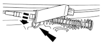 3. Pull the parking brake cable adjuster clip downward. The tensioner spring will take up the cable slack and preload the cables.
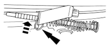 4. Push upward on the bottom of the clip to lock the adjustment. If the clip does not slide upward, move the assembly slightly to align the closest groove on the parking brake cable adjuster rod with the clip.
5. NOTE: If new cables are installed, allow 20 minutes prior to releasing the parking brake control.
Apply the parking brake control fully and release using the parking brake release handle.
6. Repeat Steps 3 and 4 to complete the adjustment procedure.
Parking Drum Brake Adjustment
1. Make sure the parking brake is fully released.
Using the release handle, release the parking brake control.
2. Remove the wheel, caliper and rotor if possible.
3. If the brake disc binds on the rear parking brake shoes, remove the adjustment hole access plug and retract the parking brake shoes using an adjusting tool.
Insert the tool at the end of the access plug slot farthest from the brake caliper. Engage the adjuster and rotate by raising the end of the tool toward the backing plate. You should be able to remove the brake disc.
4. Inspect the parking brake shoes and drum for wear, damage or oil contamination. On some 2009 models, the axle and seal were prone to leaks on the right side. On all models, make sure you inspect this seal.
5. Using a suitable brake adjusting gauge, measure the inside diameter of the drum portion of the rear brake disc. Record the measurement.
6. Using a suitable brake adjusting gauge, set the rear brake shoe and lining diameter to 0.5 mm (0.020 inch) less than the inside diameter of the drum portion of the rear brake disc.
7. Position the brake disc onto the hub.
8. Position the brake caliper and brake pads onto the anchor plate and install the two brake caliper guide pin bolts. Tighten to 25 Nm (18 lb-ft).
9. Test the parking brake for normal operation.