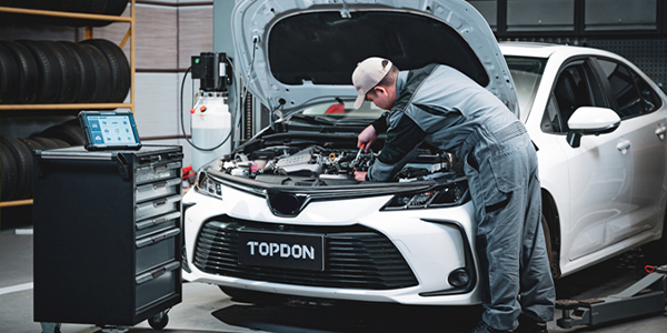
Although modern OBD II technology has simplified catalytic converter diagnostics, it’s still important to understand the basics of catalytic converter operation when dealing with a P0420 or P0430 diagnostic trouble code (DTC). DTCs P0420/P0430 indicate that catalyst efficiency is below predetermined thresholds on cylinder banks 1 and 2, respectively. In the following text, I’ll explore the basics of catalytic converter chemistry and summarize how common catalytic converter failures can be diagnosed. See Photo 1.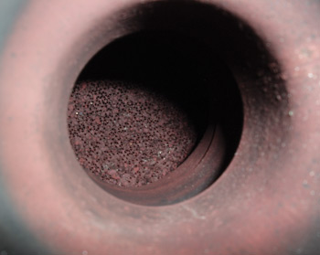
LAMBDA NUMBERS
Understanding Lambda is important because the catalytic converter neither creates or destroys atoms. Instead, it simply changes how atoms are assembled into chemical compounds. The term “Lambda” represents a stoichiometric or chemically correct air/fuel (a/f) ratio of 14.7 unit weights of “pure” gasoline to 1.0 unit weights of air. Catalytic converters operate most efficiently at Lambda because all of the gasoline and air inducted into an engine can theoretically be oxidized into water vapor and carbon dioxide.
Lambda is determined by dividing the current a/f ratio by 14.7. A “rich” 12:1 a/f ratio therefore produces a Lambda number of 0.82 when 12.0 is divided by 14.7. A “lean” 16:1 a/f ratio produces a Lambda of 1.09 when 16.0 is divided by 14.7.
Lambda is maintained by modern closed-loop fuel control systems using an upstream oxygen (O2) or air/fuel ratio (AFR) sensor to measure the oxygen content of the feed gases entering the catalytic converter. The powertrain control module (PCM) uses that data to modulate a/f ratio by changing the fuel injector opening time. Remember that a false Lambda number can result if an exhaust leak exists ahead of the upstream oxygen sensor.
FEED GASES
During the combustion process, atoms of HC and N2 are oxidized by bonding with atoms of O2. The chemical symbols “H” and “C” indicate that hydrogen and carbon exist in their natural states as single atoms, while “O2” and “N2” exist in their natural states as two atoms bonded together. The resulting combinations of HC, CO, NOx, CO2 and O2 entering the catalytic converter are called “feed” gases, which are the source of atmospheric pollution.
CATALYTIC CHEMISTRY
The function of the modern three-way catalytic converter is to convert the various compounds of HC, O2 and N2 into more environmentally friendly gases. To illustrate, gasoline is a complex hydrocarbon compound in which atoms of hydrogen (H) are bonded in various forms with atoms of carbon (C). When a 14.7:1 a/f ratio is oxidized within the confines of a combustion chamber, the theoretical exhaust product should be pure carbon dioxide (CO2), water vapor (H2O) and nitrogen (N2).
In reality, the microscopic layers of fuel (HC) touching the surfaces of the combustion chamber remain unburned. Carbon monoxide (CO) is generally formed when an insufficient amount of oxygen is available to fully oxidize carbon and oxygen into CO2. CO might also be caused by an unequal distribution of fuel within the combustion chamber.
An engine produces nitrogen oxide emissions because our atmosphere is composed of about 78% nitrogen. Under the high pressures and temperatures of the combustion process, the normally chemically inert nitrogen gas bonds with oxygen to form nitrogen oxides or NOx.
THREE-WAY CATALYTIC CONVERTER CONSTRUCTION
Although construction can vary according to engine application, the common three-way catalytic converter contains a reduction and oxidation stage. To create maximum surface area, each stage is generally a ceramic or stainless steel honeycomb substrate covered with a rough silica and alumina wash coat. Both stages of the converter are coated with precious metal catalysts that accelerate chemical reactions without themselves being consumed.
The reduction catalyst generally includes platinum, rhodium and cerium. Cerium stores excess oxygen during periods of “lean” operation that can later be used to oxidize HC and CO during periods of “rich” operation. The oxidation catalyst is generally coated with platinum and palladium. Throughout these simultaneous chemical processes, the catalysts — platinum, rhodium, palladium and cerium — remain unchanged.
The reduction stage breaks nitrogen oxide molecules (2NOx) into their component parts of O2 and N2. The oxidation stage uses some of the oxygen generated by the reduction stage to change lethal CO to non-toxic CO2 by adding an atom of oxygen. Similarly, the oxidation stage oxidizes HC by adding two atoms of H to one atom of O, which produces water vapor (H2O).
THE CATALYST MONITOR
All passenger car and light truck OBD II emissions systems built since 1996 test the efficiency of the catalytic converter by running a catalyst test or “monitor.” The catalyst monitor is a non-continuous monitor, which means the monitor runs only once during any single warm-up cycle. 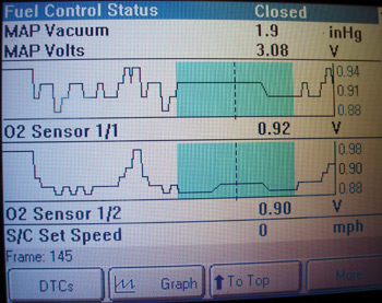
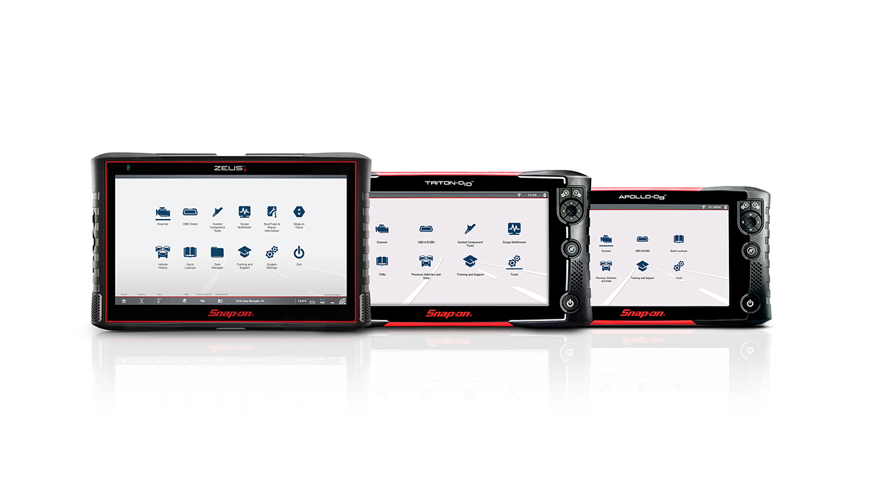
The “cat” monitor must meet a set of application-specific driving conditions called “enabling criteria” before it can run. The enabling criteria for a Honda product might include DTCs P0137, P0138 and P0141 not set, cold engine start-up completed and running in closed loop with vehicle speed at 40-55 mph for two minutes, followed by a deceleration period to 35 mph at closed throttle. See Photo 2.
Most professional scan tools indicate when the cat monitor is ready. When the cat monitor begins, the PCM performs a mathematical analysis of the difference between the upstream and downstream oxygen sensor inputs to determine converter efficiency. The math formula is also designed to filter “false” data. When efficiency falls below a predetermined threshold, a P0420 is stored in the PCM’s diagnostic memory and the Malfunction Indicator Light (MIL) is turned on.
DIAGNOSTIC SUMMARY
Catalytic converters can fail due to physical damage, normal degradation, contamination, overheating, internal disintegration and restriction in the substrate. Physical damage should be an obvious reason for a DTC P0420/0430 being stored in the diagnostic memory. Normal degradation or wear, on the other hand, varies widely among different nameplates and applications. Modern original equipment converters covered under an EPA warranty are built to last at least eight years or 80,000 miles, whichever occurs first. This warranty has been extended to 10 years and 100,000 miles in some states like California.
Converters failing with a P0420/0430 DTC under that warranty should be referred to an OE authorized dealer for warranty replacement. While OE converters will degrade, they are generally designed to last well beyond the normal EPA warranty period. Aftermarket converters have a significantly shorter warranty period and generally won’t meet the “8/80” standard.
Before replacing a converter that stores a P0420/0430 DTC, always check TSBs to make sure that downloading new threshold calibrations into the PCM can’t instead cure the problem. After replacing a converter, be sure to follow federal and state regulations regarding documentation, storage and disposal of the old unit.
Although lead, sulfur, silicon, zinc and phosphorous contamination hasten the degradation process, very little of these materials exist in modern automotive environments. To illustrate, ethyl lead is found only in racing gasoline. While sulfur can be found in some fuels, it will eventually burn away when the converter reaches high temperatures. Silicon found in plain dirt can, to some extent, contaminate gasoline. Using non-approved silicone gasket sealants commonly causes silicon contamination. Although oils containing phosphorus have been phased out, phosphorus can still be found in some motor oils designed for flat-tappet racing engines. Before replacing a converter, an engine should, nevertheless, be evaluated for excess coolant or fluid consumption to prevent possible contamination of the new converter.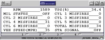
Thermal or overheating damage occurs when a cylinder misfire causes excessive amounts of unburned oxygen and gasoline to enter the converter. In general, the catalyst begins to function at 550° F and will begin to lose efficiency at 1,800° F. Temperatures approaching 2,500° F will melt the substrate. While many newer vehicles will disable the fuel injector on a misfiring cylinder to prevent overheating of the catalyst, others may not. See Photo 3.
In these cases, it pays to replace spark plugs, wires, coils and other ignition parts as a preventive measure if the catalyst substrate appears to have melted or if the PCM’s diagnostic memory contains any current P0300-series misfire codes or has misfires recorded in the misfire history.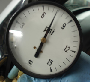
Internal disintegration can be tested by lightly rapping the converter shell with a rubber mallet. If the converter rattles, the wrap insulating the substrate against the converter shell has come loose or the substrate itself might be disintegrating. See Photo 4.
Exhaust restriction often occurs if the substrate is contaminated or if it begins to disintegrate. Restriction can become so severe that the engine stalls, or so mild that the driver barely notices a power loss during acceleration. Remember, too, that a restricted converter may not store a P0420/0430 DTC.
While other testing methods are effective, the most definitive test for exhaust backpressure is to place an adaptor in the upstream oxygen sensor port and attach a low-pressure gauge of at least 15 psi capacity. At idle, the pressure should be less than 1 psi. During a snap-throttle test, the pressure generally shouldn’t exceed 4 psi. While the P0420/0430 DTCs can occasionally be tough to diagnose, you’ll find yourself with fewer comebacks and greater profitability if you remember the basics of catalytic converter diagnostics.