Although conventional throttle position sensors attached to the throttle shaft are considered basic technology on modern engine management systems, the conventional throttle sensor plays an important role in its relationship with other sensors. The voltage inputs of most throttle position (TP) sensors may, for example, be coordinated with the barometric pressure (BARO), manifold absolute pressure (MAP), mass air flow (MAF), engine coolant temperature (ECT), intake air temperature (IAT), crankshaft position (CKP) and vehicle speed (VSS) sensors. From the combined data inputs of these sensors, the OBD I engine control module (ECM) or OBD II powertrain control module (PCM) calculates the correct electrical outputs for actuators like the ignition control module (ICM), fuel injectors, idle speed control and fuel pump.
Of course, throttle sensors don’t always produce identical symptoms when they fail because an ECM’s or PCM’s self-diagnostic strategy can be very application-specific. In addition, not all throttle sensors are identical in design or operation. Consequently, it’s important to understand how a TP sensor may control or affect an engine management system.
EARLY TPS DESIGNS
Many pre-1996 OBD I-equipped imports utilize throttle sensors in a much different way than do current OBD II models. For example, many OBD I throttle sensors incorporated a “nose switch” function that would indicate to the ECM when the throttle was fully closed. At the closed-throttle position, the ECM would operate in an open-loop condition, which meant that the spark timing and fuel control would operate at a fixed value.
As the engine warmed to operating temperature and the throttle sensor indicated to the ECM that the throttle was opening, the ECM would then go into closed-loop operation. At that point, it would begin to manage the spark timing and fuel control to simultaneously achieve maximum power, fuel economy and reduced exhaust emissions.
The fact that many OBD I TP sensors could drive the ECM into open-loop operation under closed throttle, idle speed conditions is critical because many failures, such as a defective MAF sensor, can be misdiagnosed if the technician is unaware that the ECM is ignoring many basic sensor inputs when operating in a closed-throttle, idle speed mode.
In addition, many TP sensors are more accurately described as throttle position “switches.” Because they may be combined with a vane-type air flow meter, only the closed, partial and full-throttle positions may need to be relayed to the ECM. These particular applications require very accurate closed and part-throttle voltage adjustments in order to relay the exact throttle angle data to the ECM. An inaccurate adjustment of these sensors may cause the ECM to go into a fuel-cut mode, which, in turn, may cause a part-throttle surging condition. Having more than three wires in the TP connector can identify some of these TP sensors or switches.
MODERN TP SENSORS
While a modern three-wire, TP sensor operating on a 5-volt reference power source may perform a variety of functions in on-board diagnostics, multiplexed electrical systems and electronically controlled drivetrains, the TP sensor’s primary function is to control the engine’s idle speed, spark timing and air/fuel mixture ratio.
 In most cases, the modern TP sensor is a simple, but very accurate, potentiometer that produces a voltage consistent with the throttle plate angle (see Photo 1). As mentioned earlier, many early import applications required a precise voltage adjustment, such as 0.42 volts at closed throttle, for the ECM to recognize the closed-throttle position. Providing that the voltage fell within a specific range, many later-model OBD II PCMs will “learn” the closed-throttle voltage as a reference to all other throttle positions. If the TP sensor can’t consistently repeat the learned voltage, a TP-related trouble code may be stored in the PCM’s diagnostic memory.
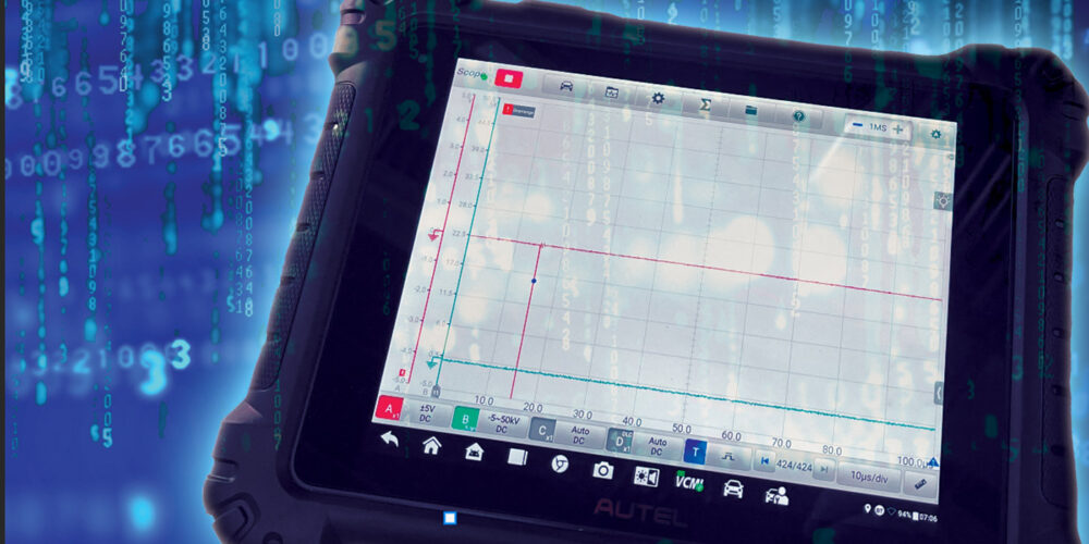
 As the throttle opens, the TP sensor relays the exact throttle angle to the PCM. Most often, the throttle angle is displayed as “TP percent” (see Photo 2). Armed with this information, the PCM controls (among many other issues) spark timing, air/fuel ratio and gear shift modulation in the automatic transmission. As the throttle opens, the transmission raises gearshift points to allow the engine to develop more torque. In addition, the transmission’s hydraulic oil pressure increases to prevent clutch slippage. Of course, the PCM is also programmed to keep the engine operating at the most efficient speed. So the subsequent gear selection is one that allows the engine to operate most efficiently regarding fuel economy and exhaust emissions.
 Throttle sensors are also designed to produce a maximum wide-open throttle (WOT) value of about 4.0 to 4.5 volts (see Photo 3). Under normal conditions, when the PCM approaches a 4.5-volt WOT signal, it goes into a “clear flood” mode, which limits the pulse width of the fuel injectors or shuts off the fuel injectors altogether.
In some cases, if the PCM receives a 5.0-volt signal, it may be programmed to determine that the TP sensor is shorted internally to reference voltage. When the PCM senses that the TP sensor is shorted, it may enter into an emergency-operating mode that overrides the clear flood command and allows the engine to start and run. In other cases, the PCM may lack that particular programming and the engine will fail to start. Most shorted TP sensors will cause a related trouble code to be stored in the PCM’s diagnostic memory.
OBD STRATEGIES
The PCM uses the throttle position sensor to evaluate other sensors like the MAF and MAP sensors. To illustrate, the PCM may use inputs from the TP, CKP (engine speed) and BARO sensors to estimate the intake manifold vacuum. Clearly, if the engine is running at 2,000 rpm at closed throttle, the PCM expects to see high intake manifold vacuum. If high vacuum isn’t present, the PCM may turn on the MIL.
Similarly, the throttle angle, engine speed and grams per second air flow through the MAF sensor should correlate. If the TP sensor is producing a known-good voltage value, the PCM may decide that the MAF is defective if the indicated air flow is out of line with the engine speed and throttle position. In some operating strategies, however, a faulty TP sensor may create a DTC that indicates other sensors or actuators are at fault, which may not be the case.
FAILURE PATTERNS
Because the modern TP sensor contains a metal brush that mechanically contacts an electrical winding, it does wear out. In city driving, the most wear occurs at relatively low throttle angles and vehicle speeds.
In other cases, the sensor may intermittently stick in an open or partially open throttle position, which causes the spark timing, fuel injection pulse width and transmission performance to become inconsistent with actual operating conditions. In some applications, the PCM may employ a default or failure mode strategy to deal with this situation. In other cases, the vehicle may operate very poorly until the faulty TP sensor is replaced.
One of the most common TP-related performance complaints is a fluctuating or excessively high engine idle speed. This failure pattern occurs when the TP sensor doesn’t return to the “learned” closed-throttle voltage. Here again, the exact response of the PCM to the failure depends upon the PCM’s operating strategy.
In some cases, the PCM may command the idle air control (IAC) valve to open to maximum position, which causes the engine to idle at nearly 2,000 rpm. In other cases, the condition may appear as merely an unstable idle condition.
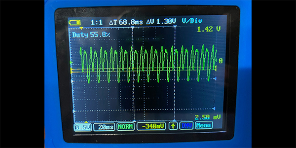
A throttle position sensor may be evaluated by using a digital volt-ohm meter (DVOM) with a bar scale, a scan tool with a graphing capability or a digital storage oscilloscope (DSO) with a spike or glitch detect feature. The DVOM or scan tool can be invaluable for precisely measuring a TP sensor’s closed-throttle voltage or for detecting a TP sensor shorted to reference voltage.
On the other hand, the update capabilities of the DVOM or scan tool may not detect a momentary voltage dropout. The DSO, on the other hand, can capture a momentary voltage drop-out as the throttle plate is gradually opened. In any case, having the right equipment and knowing how to use it is essential for accurate throttle position sensor diagnosis.