By Olle Gladso, Vladimir Postolovskyi and Andrew Bezhanov,
Contributing Writers and Instructors at Riverland Technical and Community College in Albert Lea, MN
Simple techniques will often allow us to diagnose problems without a significant investment of time and effort. Knowledge, experience and observation are at the core of successful unconventional diagnostics. The ability to see and understand things that others may miss will make the difference between your shop and your competition. 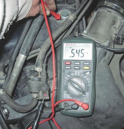
Unconventional methods do not necessarily involve the use of expensive equipment and devices. It can be just a simple observation and some “tricks of the trade.” For example, you can hold your hand close to the exhaust pipe, which could help determine if the engine is misfiring. However, unless you have the ability and knowledge to combine methods — unconventional as well as conventional — depending on the task at hand, you may not be successful in your diagnosis.
Let’s begin by exploring unconventional uses of a digital multimeter (DMM).
For our first example, we’ll use a situation where the scanner showed a code had been set for a faulty tank vent valve. Normal diagnostics often involve checking the resistance of the valve, presence of system voltage and the control module’s ability to activate the valve by using a scanner with bidirectional control ability. The resistance of the valve is normal, the power supply is normal, but activating the valve using the scanner doesn’t work, so where is the problem? 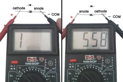
Perhaps there is an open in the circuit wiring somewhere? You can dismantle the vehicle sufficiently to gain access to the engine control unit (ECU), find the right pin on the connector, and, using an ohmmeter, check the continuity between the control unit and the valve.
If the output transistor in the ECU (such as the tank vent valve circuit) has an integrated diode in it (used for voltage spike suppression), the diode, along with our knowledge of the system, can help us find potential wiring problems as well as problems within the ECU.
To do this, turn the ignition switch to the off position. On your multimeter, select “diode test.” Connect the multimeter’s red lead to the vehicle ground, and the black lead to one of the pins in the harness connector for the vent valve. If the meter shows practically zero voltage, it is most likely that we are on the power supply pin in the valve connector. If the display voltage was approximately 550 mV, then the wiring to the control unit is good and the output transistor is most likely OK. If the meter displayed an open circuit, then there is most likely a break in the wiring. If the meter showed close to zero on both pins, there is a short to ground somewhere. The short to ground could be either in the wiring itself, or in the control unit. 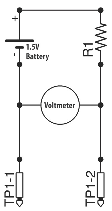
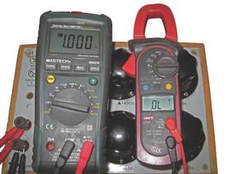
We cannot directly test the transistor itself. However, since the protection diode is often built into the transistor, then, in case of damage, both are usually damaged. The diode is connected across the transistor in reverse polarity. In order to check the diode, we connect the DMM test probes in reverse polarity as well. With properly connected test probes, the current will go through the diode, and the display will show the forward voltage drop of the diode. See Figure 1, in which the DMM shows that the wiring to the control unit has continuity.
 How does this work?
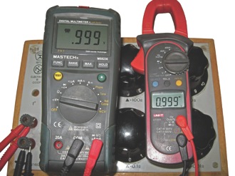
Figure 2 shows a DMM in the diode test mode. In this mode, the meter delivers approximately 1.5V to the meter leads. The voltage is delivered through a fairly large value resistor and the meter circuit reads the voltage at the probe leads. (See Figure 3.) If the leads are shorted together, or they are connected across a small resistance, the meter will read 0V or close to it. The reading is the voltage at the meter leads after the resistor. In this mode, any voltage larger than 999 mV will cause the meter to read “1”. The “1” sign by convention means open circuit.
In Figures 4a and 4b, the DMM on the right is in the “diode test” mode, and the DMM on the left is set to measure voltage. Both meters are connected to a resistance box, which is a test device that can be used as a variable resistor. If we reduce the resistance of the resistance box, the voltage output from the DMM in the diode test mode will be less and the display will show a voltage value lower than 1,000 mV. A DMM in the diode test mode (and to some degree also in the resistance test mode) can be used as a low voltage source that can provide 0-1,000 mV, to simulate some sensors.
In another example, the scan tool showed that a diagnostic trouble code (DTC) for the knock sensor had set. There are several possible causes for the DTC, such as a bad sensor, bad wiring, bad control unit or the sensor itself is not properly torqued. 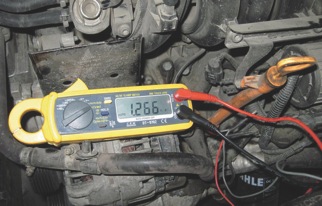
The sensor can be checked with a DMM and here is how: The sensor itself has a very high internal resistance and normally the DMM cannot measure it. However, some manufacturers integrate a resistor into the knock sensor to be able to test the circuit’s integrity (shorts, opens, low and high resistance). The value is commonly 50-100 k ohms.
How can a knock sensor without the built-in resistor be checked? The piezo element in the knock sensor is, in addition to a voltage-generating device, also a capacitor. We can measure the capacitance, using the DMM. Most knock sensors have a capacitance of approximately 900-1,300 pF. The wiring from the control unit to the sensor may add a significant amount of capacitance. This capacitance may need to be accounted for.
The knock sensor can be checked to some degree simply by measuring the output voltage from the sensor when tapped. This method does have some significant drawbacks: The signal from the knock sensor is of very short duration. Because the DMM needs some time to sample the signal and cannot continously sample it, we will get different measured voltages for each tap, even if we tap the sensor with the same effort. If the DMM is equipped with a function that records and displays maximum voltage, that function can be helpful in this case. The knock sensor is often mounted on the cylinder block in an inaccessible location. Tapping on the sensor may not be possible for that reason.
High-end DMMs such as the meter shown in Figure 5 tend to have a number of functions in addition to the basic ACV, DCV, Ohms, diode test, DCA and ACA modes. Some additional functions to look for are temperature, frequency, transistor and capacitance tests. Some DMMs will also remember the minimum and maximum values of any given measurement as well as a measurement hold mode where the display shows the last value before the test leads were disconnected. Medium-range meters may only have a max hold mode and no min hold mode, however. 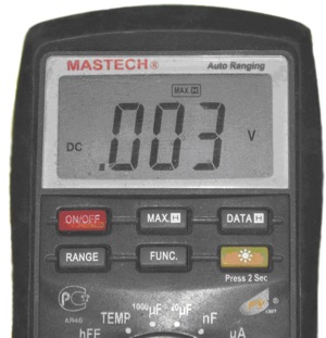
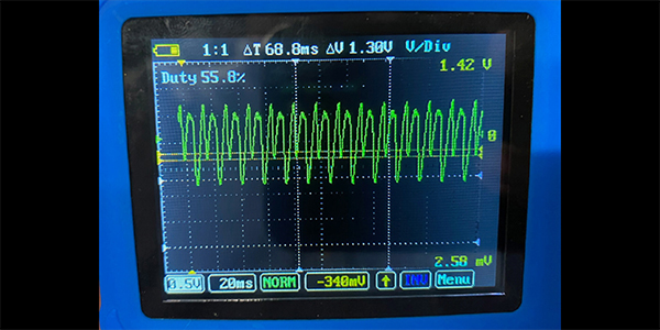
The max hold mode can be useful to us in many cases. For example, you can use the max hold mode to check the voltage on the stop lamp bulbs without needing an assistant. Enabling this mode on the multimeter, we can move to press the brake pedal. A multimeter will measure and memorize the maximum voltage present at the bulbs while you depress the brake pedal. See Figure 6.
Sometimes we want to be able to measure the minimum voltage in a given circuit, but many DMMs can only measure max voltage. There is a way around this — we can “trick” the meter into remembering the minimum voltage — just connect the meter test leads backward. See Figure 7. 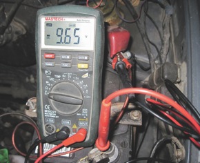
We connect the red test lead to the negative part of the circuit and the black test lead to the positive part of the circuit. The multimeter will show a negative voltage, but we know that this is not the case. If we are suspecting a bad connection somewhere, we can twist and bend wiring and connectors without having to constantly watch the meter for voltage dips. If the meter shows anything less than the nominal voltage in the circuit, we know there is a bad connection somewhere in what we just tested.
We can also use this technique to measure and record voltage drops when starting the engine. This can be very useful when diagnosing complaints of poor starting or charging. The actual starting of the engine may take less than one second, so it may be desirable to disable the sluggish auto range function in the DMM. Just set the range to something on the order of 1 to 2 volts or so, since the voltage drop should be very small. If the meter shows OL when performing this test, increase the range and try again. One problem with this technique is that the max hold function will show 0 volts if we disconnect the multimeter probes, accidentally or otherwise. This is because 0V is larger than a negative voltage.
The next installment of Unconventional Diagnostic Methods will tackle more diagnostic tips and tricks for your DMM.