It is unfortunate that today misfire analysis can be a hit-or-miss concept on many of today’s engine families. If one views several misfire failures, and documents the behavior of fuel trims, it is reasonable to state that ignition misfires do not have a significant impact on them, whereas fuel-related issues create a significant impact.
There are many traditional techniques for determining the cause of misfire activity in a cylinder. A few traditional tools that come to mind are the compression gauge, cylinder leakage tester and vacuum gauge. It is also interesting to cite a few non-traditional tools for reference as well. An in-cylinder transducer can be used today to look at cylindrical pressure and vacuum in a cylinder to evaluate engine mechanical integrity. A transducer can also be placed in the exhaust to look at exhaust pulse activity as a means to evaluate engine mechanical integrity. I was also amazed to find that there existed computer software to evaluate misfire activity on an engine.
These non-traditional tools represent the move toward more efficient ways of obtaining an accurate diagnosis in less time. The modern-day engine has components that are very difficult to access in reference to analysis and repair. The traditional testing takes more time to gather the data needed to make a logical decision.
This article represents the third in my series of investigations on the top emission-related codes as indicated by many states. Our goal in this report is to discuss the characteristics of the P0302 code as it applies to many manufacturer products today.
A suggested strategy for misfire analysis is to first perform engine mechanical tests. This will be defined by three sub-tests: mainly relative compression, cranking vacuum and running compression (cylindrical pressure). This was a great experience to witness the results taken from two subject vehicles as a comparison. The traditional compression gauge was compared against the modern-day in-cylinder transducer. The subject vehicles — 2008 Chevrolet Uplanders — were located at a local fleet, and we started with the known-good vehicle first to set up our baseline for analysis.
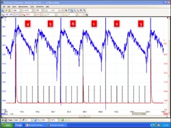
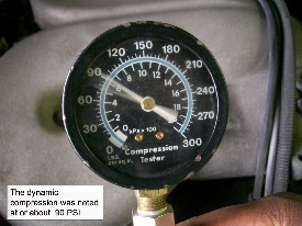
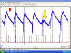
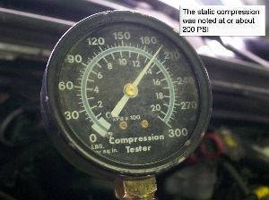
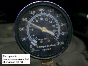
A relative compression test was performed first; the scope pattern showed consistent activity. See Figure 1. There was no abnormal activity noted. The second test was a cranking vacuum test; the scope pattern showed good consistent activity. The final test performed was a comparison between the compression gauge and in-cylinder transducer; the static compression reading per the gauge was 200 psi. The running compression reading per the gauge was 90 psi. See Photos 1 and 2. The same tests were run with the transducer and similar readings were obtained as noted per the gauge. The running compression pattern was analyzed for cam timing issues; the pattern showed no abnormalities. We have now obtained a baseline to work with in terms of test numbers. 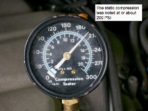
Relative Compression Test — Known-Good Vehicle
• We are synched on cylinder #4.
• We are looking for good consistent activity per the humps.
• A good peak-to-valley measurement should also be noted: 30 amps minimum.
We are now ready to test our second vehicle, which is our suspect vehicle. A code P0302 was stored in its memory, indicating possible misfire activity on cylinder #2. The first test performed was a relative compression test. The test results did indeed show that there was a problem within the #2 cylinder (see Figure 2); it is clear from the test results that this is a mechanical issue.
A cranking vacuum test is now performed and it also shows a slight issue in the scope pattern. See Figure 3. 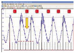
A final test is performed using the compression gauge and in-cylinder transducer. The compression gauge shows a cranking compression of 200 psi and a running compression of 90 psi. See Photos 3 and 4. Does this sound familiar?
The transducer is now placed in the cylinder and a strange cranking pattern is noted. The running compression pattern is also recorded and it appears to be normal.
Final Analysis
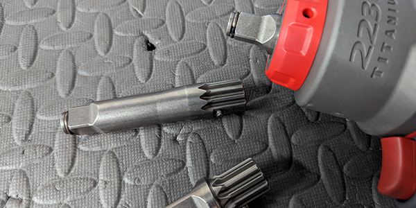
The cranking pattern is an example of a cylinder with an upper end sealing issue. The most likely cause is the valve(s) are not seating properly. See Photo 5. The compression gauge shows that the cylinder compression cranking and running is good.
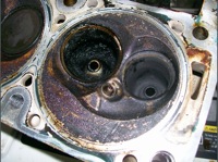
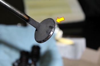
It is interesting to note that the compression gauge showed the same values as the known-good vehicle. The transducer showed that we had a true mechanical issue with our suspect vehicle. The cylinder head was disassembled from the engine and a close visual inspection was made. The inspection revealed that we had a burnt exhaust valve (Photo 6).
Why did the compression gauge show that we had good compression on both vehicles? I think this can open up lines for discussion. Please feel free to e-mail me your thoughts. This Pulling Codes case is now closed.