 You just performed an alignment and all the angles are within the specifications on the screen. As you start on the test drive, the ABS and/or stability control light comes on. What happened? You might have forgotten the electronic angles.
The modern vehicle is always measuring what the vehicle is doing and what the driver wants the vehicle to do. It does this with sensors that measure the driver’s interactions with the steering wheel, brake pedal and gas pedal. It measures the results of these actions with the yaw, acceleration and wheel speed sensors. If some of these sensors are not calibrated after an alignment, what the vehicle is doing may come in conflict with what the sensors are reading. This is why is using a scan tool after an alignment on the majority of late-model vehicles is a critical step.
STEERING ANGLE
Measuring the steering wheel position angle and rate of turn, which are critical for Electronic Stability Control (ESC) systems, is the job of the Steering Angle Sensor (SAS). The scan tool will typically display the information in degrees.
The SAS is typically a part of a sensor cluster in the steering column. The sensor cluster will always have more than one steering position sensor; some sensor clusters have three sensors for redundancy and to confirm the data. It’s important for the ABS/ESC module to receive two signals to confirm the steering wheel’s position. These signals are often out of phase with each other.
Analog SASs are similar to throttle positions sensors. SASs are wired with a 5-volt reference, chassis ground and signal output. To test the SAS, you have to back probe a connector that is typically under the steering column.
As the steering wheel is turned, the SAS produces a signal that toggles between 0 and 5 volts as the wheel is turned 360º. As the wheel is turned lock-to-lock, the voltage will reach 5 volts three times and 0 volts three times.
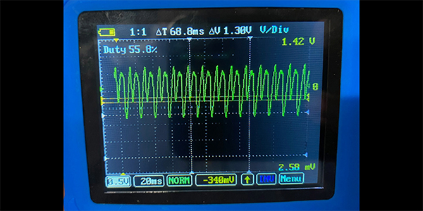
Often, other wires for the torque sensor for the electric power steering go to the SAS sensor cluster. With meters connected to the signal wires for the two SAS sensors and their commons connected to the ground, it’s possible to observe the 0- to 5-volt signal and how the signals are out of phase for the sensors.
With the wheel turned fully to the right, the voltages don’t match, which is perfectly normal. On most vehicles turning to the right creates a positive voltage and to the left creates a negative voltage; but some cars are opposite. The scope pattern shows the signal traces from the two sensors on top of each other. This can be helpful when comparing the signals and if one is flat lining.
A digital SAS is often called a “contactless sensor.” This type of sensor uses LED light, a wheel that acts as a shutter and an optic sensor that measures interruption in the light, just like a distributor on a Chevy LE1 V8.
The signal for these types of sensors is a digital square-wave signal. The frequency of the voltage changes depending on the speed the wheel is turning. The sensor clusters for these sensors often contain a third sensor just to measure if the wheel is centered. With the wheel straight, the voltage is close to 0 volts. When the steering wheel is moved off center, the voltage goes high.
Some SAS clusters and sensor modules connect to a Controller Area Network (CAN) bus. The SAS module can connect directly to the ABS/ESC module on a CAN bus or it can be part of the overall CAN network in a loop that connects various modules in the vehicle.
The best way to test modules on a high-speed CAN bus is with a scan tool. Most tools are able to look at the data directly, but can’t look at the datastream directly for an SAS due to software issues with the tool.
On a direct-type SAS CAN sensor, you can see the sensors communicating with ABS/ESC module as the wheel is turned. While you can see they are communicating, it’s impossible to tell what is being communicated.
RESETING STEERING ANGLE SENSORS
Many vehicles require the SAS be reset or recalibrated after an alignment is performed or parts in the steering system are replaced. There are three types of reset procedures. First, systems that self calibrate. Second, vehicles that require specific wires or buttons be pressed. Third, systems that require recalibration with a scan tool.
Even if the SAS is out of calibration, most vehicles have ways of sensing if it is traveling in a straight line. If the angle is far enough out of range, it might set a trouble code and disable the ESC system.
SCAN TOOL STEERING ANGLE SENSOR RESET
There are many options for scan tools to reset SASs. Some tools are even integrated into an alignment system, but most tools recommend that the calibration be performed on a level surface. Also, it’s a good idea to perform a lock-to-lock turn to complete the calibration.
While performing the Zero Point Calibration on Toyota vehicles, do not tilt, move or shake the vehicle. The vehicle must remain in a stationary condition throughout the entire process. Be sure to perform the procedure on a level surface with an inclination of less than 1%.