Saab engine technology has evolved through the years, but the same basic design of the original B202 engine is still used in today’s Saabs.
When the 16-valve 2.0L engine (B202) was developed in 1984, I was one of 10 people chosen from the East Coast area by Saab in the United States to attend a special crash course to learn about the new engine and fuel management controls. It was a “first” to use the new LH fuel system backed by an intercooled turbocharger that developed 160 hp.
When the engine was released in 1985, it was available only in turbocharged form. The following year, a normally aspirated version was used in the S series.
To me, this was highly unusual to see a completely new engine having high positive combustion pressures from a Garrett T3 turbocharger linked with an air-to-air intercooler.
The engine was very durable and proved to be tough, as these engines were acquired directly from the factory and installed into the Skip Barber race cars that won many championships for a two-year timespan.
In 1991, the displacement was increased to 2.3L by changing the stroke while keeping the same bore size. This setup was offered only in the 9000 model. The engine used direct ignition linked with an LH Bosch fuel system for remarkable performance.
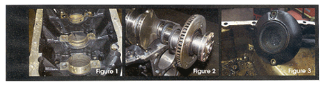
The engine block was redesigned to accommodate the balance shafts and have stronger webbing at the main bearing journals for the added torque (see Figure 1). The cylinder head was such an ingenious design from the start that only minor changes were made for proper lubrication.
The engines used from 1991 to 1993 were basically the same. They were called a long block, measuring a 1/2-inch longer than 1994-’98 2.3L engines. The long- block 2.3L engines had a few problems, including the balance and timing chain design, but they were revised. What the Saab engineers did for the 1994-’98 2.3L engine was to make a bulletproof, long-lasting engine. The engine was skillfully perfected to a point that even the late race cars use the block, head, crankshaft and injection system (also the same setup that we use in our race cars).
The injection was also upscaled and called Trionic 5. The first year for it was 1993, but it had traction control that had problems and could not adapt to normal driving conditions, so it was dropped. Although it came back in 1995, it was dissolved for some strange reason.
The Trionic fuel control unit consists of fuel control, ignition control (DI) and turbo control for knock detection (APC), and is one neat package. In 1994, the 2.3L engine was the first to be equipped with an internal crankshaft aperture wheel and outside magnetic pickup for precise engine timing control (see Figure 2).
GETTING STARTED
Before any engine work is performed in our shop, we try to determine why the engine failed. Has the engine overheated to the point of major rebuilding? This is very important as the cylinder head could have internal cracks, which would not show up even when tested at a machine shop.
Was the engine run without oil pressure? We see more engine failure now because of lack of oil changes. This is a major problem because the oil pickup screen in these models is so fine and very close to the bottom of the oil pan, which causes oil pump starvation. The sludge forms an anthill-like sediment that clogs up the screen (see Figure 3). When this happens, it takes no time to have catastrophic engine failure when the vehicle is driven at highway speeds.
In this article, I will review the rebuilding procedures and trouble areas to address when a major teardown is necessary on a long-block 2.3L 9000 engine.
ENGINE REMOVAL – 9000 SERIES
It’s recommended that when removing the engine in the 9000 series, you should take out the entire powertrain at the same time.
Pull out both axle halfshafts and place them in a clean area (grease flows out of them).
Remove the battery, tray and cables from the starter and alternator.
Remove the front exhaust pipe from the car. It’s easier to remove the A/C compressor and move it to the side.
Remove the injection harness from the fuel control unit and drape it over the engine.
Pull off the fuel lines and plug them. Then remove the vacuum lines.
Take off the alternator, bracket and all of the engine mount bolts.
Remove the power steering pump (leave the lines on so you won’t have oil everywhere).
If the car is a standard, remove the shifter tapered pin. If it’s an automatic, remove both the shift cable and kickdown cable from the throttle housing.
Remove the oil filter housing from the engine block and set it aside.
Drain the coolant and oil from the engine.
Pull off the right front inner plastic wheel well.
If it’s an automatic, remove the cooling lines from the cooler and drain them.
Fit a chain or lifting device to the engine and equal the weight so the engine is even.
The hood can sometimes get in the way. If it does, just pull off the gas struts and set the hood back with the assistance of a helper.
Pull the engine out and place it on a worktable. Remove the transmission and then place the engine on a stand.
ENGINE TEARDOWN
Before I tear down to the engine block, I steam-clean the outer surface to remove grime and loose particles, or I drop it into my high-pressure power wash tank.
Remove the valve cover and oil pan.
Remove the timing chain sprockets and head bolts. Don’t forget the chain tensioner.
Take off the exhaust manifold with turbocharger attached.
Take off and set aside the intake manifold and wire harness.
Remove the cylinder head and place it into the wash tank.
Remove the timing cover and oil pump.
Place all the sprockets and chains on the bench and remove the balance shafts.
Remove all the connecting rod caps and draw out the piston assemblies.
Take off all the main bearing caps and the rear main seal cover. Pull out the crankshaft.
Knock out all the freeze plugs and remove all oil pressure feed plugs.
The engine block has two end plugs for the balance shafts. Remove both and knock out the bushings for replacement. (This step is very important for proper oil pressure.)
Clean the engine block inside and out, taking out all oil deposits and sludge from the oil passages.
ENGINE BLOCK AND CRANKSHAFT PREPARATION
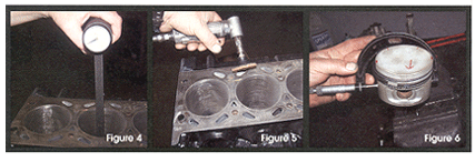
Check for cylinder taper and out-of-roundness. You will need a special cylinder bore gauge for proper measurement (see Figure 4). Look for scoring of the cylinder walls. If you detect any, boring and honing should be done and the pistons should be replaced with oversized pistons. If the cylinders and pistons are in good shape, it’s better not to touch the cylinder with a glaze breaker or a hone. Leave the surface alone!
When cleaning the gasket surfaces, be careful not to take off any metal from the block when using scuff pads with a high-speed angle grinder (see Figure 5). This could lead to many oil leaks.
If the engine had a bad case of oil starvation, the block should be checked for proper crankshaft alignment. This procedure, called line boring, is done at many automotive machine shops.
out-of-round is detected, the crank should be sent out to a machine shop for proper grinding and fitted for oversized bearings.
Check the thrust area on the crankshaft for scoring and inspect the block for worn marks where the bearings are inserted.
Before the crankshaft is sent out for machining, remove the aperture wheel and set it aside with the four special Allen screws.
Crankshaft clearance should be between 0.002 to 0.0015 inch (0.051 to 0.038 mm).
PISTONS AND CONNECTING RODS
When checking for worn areas on the pistons, the measurements are carried out at 0.787-inch (20 mm) front the bottom of the side skirt (see Figure 6). The piston should be around 3.541 inch (89.94 mm). The bore size should not exceed 0.0025 inch or 0.07 mm. Saab offers different class pistons to help in matching to the bore size. The lower part of the block is stamped at the factory for fit. A larger class could be fitted if the bore is worn and honing was performed. The pistons start out as class A, B, AB then C, with class A being the smallest and the others climbing to 0.005 inch (0.14 mm).
Checking the ring grooves for proper piston ring fit is never a problem unless broken rings were at fault.
Cleaning of the piston ring groove is a must to achieve correct fit. I just use part of an old ring, taking the time not to take off any piston material.
Check for cracks and worn areas on the pistons after extensive cleaning has been done.
The connecting rod/piston assembly utilizes a full floating wrist pin with only one lock clip on each side.
The connecting rods should be sized at the machine shop as well.
When installing the rings on the pistons, take extreme attention not to over-expand the center ring, as it will crack.
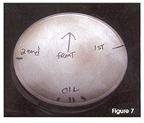
Stagger the rings on the pistons as shown in Figure 7.
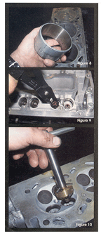
When installing the pistons into the bores, I use the factory installation tool #7862237. This tool is tapered, made for the standard-size pistons and aids in the rebuilding process (see Figure 8).
Drench the pistons/rings with light motor oil before installation, which will aid in ease of assembly.
Tighten the connecting rods to 45 ft.-lbs. and the main caps to 90 ft.-lbs.
 CYLINDER HEAD RESURFACING
Before the camshafts are removed, stamp the caps so you can put them back in the proper locations. Since the factory numbers are not stamped clearly, taking this extra step will make for a faster installation when assembly time comes.
Remove all valve hydraulic lifters and set them aside.
Remove all valve springs and spring washers.
Remove the valve seals with a special tool #8645333 (see Figure 9).
Clean and inspect the valves, and number them corresponding to their locations.
The valve guides never have problems unless the valves were bent by piston interference.
If that is the case, and they were cracked from angle impact, they must be replaced.
Look at the valve seats for pits and irregular markings. They may need to be cut with tool #8755663 (see Figure 10).
The valves can be cut on a valve grinder, or purchased from Saab or other part sources. They are reasonably priced for the important job they perform.
wn time – and time is money! I have a Bridgeport table and developed a 7-inch fly cutter and cylinder head fixture to fit onto it to fly-cut the head with ease (see Figure 11).
On turbocharged engines, try not to take off much material from the head, as early detonation could result. (Try not to take off more than 0.007 inch [0.19 mm] of material.)
Blow off all metal filings and install the valve guide seals with factory tool #8393803 (see Figure 12).
TIMING CHAINS AND BALANCE SHAFTS
Replace both the timing chain and balance shaft chains with all ramps and guides. The tensioners should be checked and cleaned. If any hitches or worn areas exist on the tensioner plungers, they should also be replaced.
Replace the balance shaft bushings and block end caps.
This is a good time to install all freeze plugs in the block.
Install the balance shafts in their proper location.
hain has yellow markings to aid in assembly.
Install all ramps and guides with the balance shaft chains in their particular locations.
Check the timing chain cover for worn marks on the oil pump drive gear area. Check the pump gears for signs of scoring and markings, and replace as needed.
When installing the cylinder head, don’t forget to have the camshafts in zero position and the piston on top-dead-center position. Tighten the head bolts down to the manufacturers’ specs.
Install the timing chain, sprockets and timing cover. Use an anaerobic sealant, rather than silicone, on gasket surfaces. When installing the valve cover rubber gasket, use a spray adhesive to hold the gasket on the cover for easy installation.
On any engine rebuild, it takes time and special tools to do the repairs the correct way. Investing in the necessary tools and equipment will enable your repair shop to make huge profits, reduce comebacks and ensure customer satisfaction with the repair.