Applies To: All 1998-2003 Accord V6, 1999-2003 Odyssey and 2003 Pilot models.
 If oil is leaking from the front, middle or rear of one of the above engines, it may be due to the cast aluminum engine block may be porous in spots. Depending on the location of the leak, seal it with JB Weld or 3-Bond-coated sealing bolts.
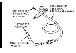
Note: For some problems, the VTEC System Test Tool (P/N 07AAJ-PNAA101) can be used to pressure-check the engine block for oil leaks. A similar tool was first used in 1992 to check the rocker arms on VTEC engines (see Service Bulletin 91-038, VTEC Inspection Tool).
If your shop does not have a VTEC System Test Tool, order it from your parts center. The tool consists of a gauge with regulator, a hose and a coupler.
If your shop does not have an adapter hose (P/N AT77), order it from the Honda Tool and Equipment Program. See Figure 1.
Parts Information
Timing Belt Adjuster Pulley Bolt (except 2003 Accord V6): P/N 14551-P8A-999
Timing Belt Adjuster Pulley Bolt (2003 Accord V6 only): P/N 14551-RCA-A01
Engine Side Mount Bracket Bolt: P/N 95801-10085-99
Transmission Mounting Bolt (2 required):
P/N 95701-12070-99
 Repair Procedure
Most engine oil leaks can be seen when you disassemble the suspected area. But, if you want to pinpoint the exact location of the leak, use a powdered leak detector (best for suspected bolt hole leaks) or do a pressure-test with the VTEC System Test Tool (best for suspected block porosity).
Leak Testing With a Powdered Leak Detector (P/N 20165)
1. Clean off residual oil and grease from the engine with engine degreaser.
2. Disassemble the engine enough to expose the area of the leak.
3. Spray powdered leak detector on the area.
4. Reassemble the engine, start it and run it for about 5 minutes.
5. Shut off the engine and inspect the leak area. Once you find the leak, go to Confirming the Leak, and use the chart to determine whether to follow Repair Procedure A or Repair Procedure B.
Leak Testing with the VTEC System Test Tool
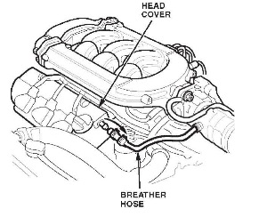
1. Disconnect the breather hose connecting the front head cover to the air inlet tube. See Figure 2.
2. Remove the oil pressure switch from the oil pump.
3. Screw the adapter of the VTEC tool into the oil pressure switch hole.
4. Connect the VTEC tool to shop air regulated to no more than 40 psi.
5. Brush soapy water on the suspected porous area (best for vertical surfaces) or fill the area with soapy water (best for a suspected leak in the engine valley).
If the area bubbles, you’ve found the leak. Go to Confirming the Leak, and use the chart to determine whether to follow Repair Procedure A or Repair Procedure B.
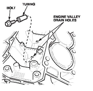 Note: To fill an engine valley section with soapy water, plug the drain hole in the valley with a piece of tubing (P/N 36285-P8A-A00) around a 6 x 15 mm bolt. See Figure 3.
6. After you pressure-test the block and make the needed repairs, pull fuse No. 11 (15A) from the driver’s under-dash fuse/relay box (to disable the ignition system), then crank the engine for 10 to 15 seconds; this ensures the engine bearings are lubricated before you start the engine. After you crank the engine, reinstall the fuse.
7. If you can’t find the leak with this method, use the powdered leak detector.
Confirming the Leak
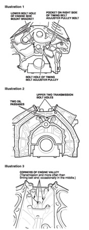
The engine may leak at any of six known areas. See Figure 4. Confirm the leak with this chart, then repair it using Repair Procedure A or B.
Repair Procedure A
1. Remove and discard the original bolt(s).
2. Install the appropriate coated bolt(s) (see Parts Information), and torque them as indicated:
– Timing Belt Adjuster Pulley Bolt: 44 Nm (33 lb.-ft.)
– Engine Side Mount Bracket Bolt: 44 Nm (33 lb.-ft.)
– Transmission Mounting Bolts: 73 Nm (54 lb.-ft.)
 3. Reassemble the engine, start it and let it run for 20 minutes. Then shut it off and confirm that the leak is gone.
Repair Procedure B
1. Thoroughly clean the area to be patched. This is vital for good bonding of the adhesive.
2. Follow the manufacturer’s directions for preparing the JB Weld (P/N 8265-S) adhesive.
3. Spread a generous amount of adhesive on the leak area and 1-2” surrounding it.
4. Reassemble the engine, making sure not to disturb the adhesive.
5. Let the adhesive set for at least 24 hours before you start the engine. This is vital because engine oil pressure will try to push through the repair.
6. If you pressure-tested the block, pull fuse No. 11 from the driver’s under-dash fuse/relay box to disable the ignition system. Then crank the engine for 10 to 15 seconds; this ensures that the engine bearings are lubricated before you start the engine. After you crank the engine, reinstall the fuse.
7. Start the engine and let it run for 20 minutes. Then shut it off and confirm that the leak is gone.