Real Cars. Real Cases.
The vehicle was a 2006 GMC 2500HD/4WD/6.0/VIN U with just over 105,000 miles on the odometer. The customer said he was driving the truck and it sputtered and stalled as he was pulling up to a light. It restarted and he made it through the light, then it quit and would not restart.
He had it towed back to his house, where a friend with a code reader offered to aid in the diagnostics. This is where the story gets vague. There was a code for either the crank or cam sensor and knock sensor codes, but the customer kept changing his story, so all of this really didn’t mean much at this point.
Somewhere in the process, the engine would no longer crank, so his friend replaced the starter, which did in fact fix the cranking problem. Then, the story got really skewed with descriptions of the sensors, the owner trying to replace one and something getting broken, so the owner had it towed to me.
He told me that they were baffled, so his friend with the code reader decided to remove a bunch of fuses and relays in the underhood fuse panel and switch them around. Along the way, the codes were cleared and the battery was disconnected to replace the starter. Oh, and finally, he dropped a blue-handled pry bar somewhere behind the engine and it didn’t fall out so he asked if could I find that, too!
My initial inspection of the vehicle yielded a half-used can of mass air flow sensor cleaner on the front seat, a disconnected camshaft position (CMP) sensor and a broken oil pressure sensor (both of which are located at the top of the bellhousing just behind the intake plenum). The camshaft sensor hold-down was bent upward and the bolt for it was in the console inside the truck.
I checked for trouble codes and there was a DTC P0342 CMP sensor circuit low-voltage code, which made sense since it was unplugged. I plugged it back in and cranked the engine. Cranking speed was good and sounded normal, and I had an engine RPM reading on my scanner, but it didn’t even give a remote hint about starting.
When turning the ignition on, I could hear the fuel pump relay click on for about one second and I could hear the fuel pump run. A backyard “depress the Schrader valve with a pocket screwdriver” pressure test determined enough for me to be confident there was indeed fuel pressure, so I began to wonder what all the original codes actually were and if there was a problem with the cam or crank sensors. In case you were wondering, I would normally check fuel pressure the right way, but didn’t have my pressure gauge with me (long story). Not knowing if the CMP sensor was bad or had been damaged by prying, and not being immediately familiar with the systems on the truck, I decided to look at the troubleshooting for the CMP sensor code and do some additional research.
Not knowing if the CMP sensor was bad or had been damaged by prying, I decided to look at the troubleshooting for the CMP sensor code and do some additional research.
Reading the CMP sensor circuit description, I learned that the 1X signal is used by the powertrain control module (PCM) to determine if the cylinder at top dead center (TDC) is on the firing stroke or exhaust stroke. The PCM, however, can determine TDC on all cylinders based on the 24X signal from the crankshaft position (CKP) sensor alone, and the engine will start without a CMP sensor signal as long as it receives the CKP sensor 24X signal.
No CMP sensor signal may cause the symptom of a long crank time, but the engine would start, so this would eliminate the CMP sensor from being a problem. But just to be sure and for my own personal knowledge, I decided to utilize the DTC P0342 diagnostic flow chart to check a couple things.
The flow chart for DTC P0342 was based on the engine starting, which it would not do, but it also outlined checking the reference voltage and sensor circuits, as well as observing the CMP sensor high to low-voltage transition parameter on a scan tool.
The reference voltage was good, and I was able to view the high to low voltage transition during engine cranking, so I was confident that the CMP sensor and its signal to the PCM were both OK and there was no need to go any further down this path.
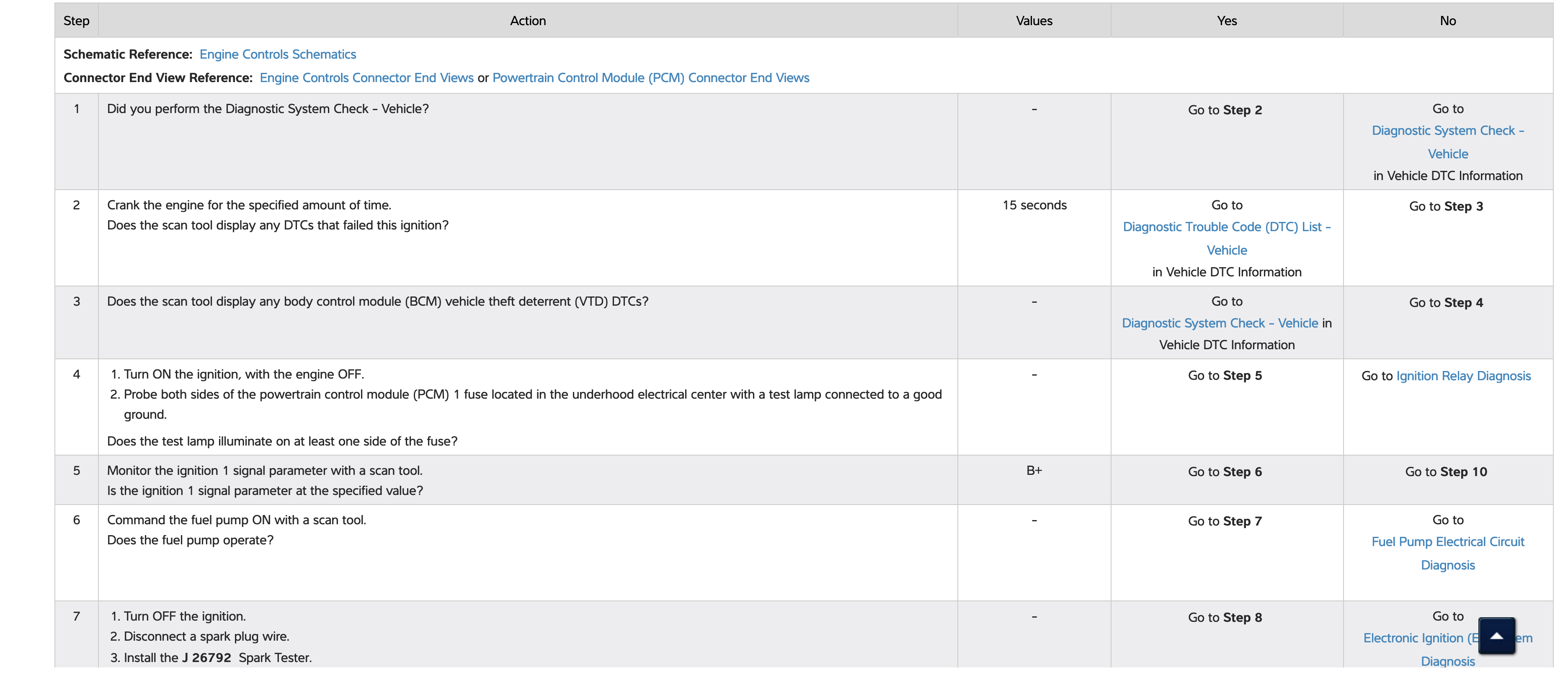
It was time to utilize the “engine cranks but does not run” flow chart for the vehicle. This procedure assumes that the battery is fully charged, cranking speed is acceptable and there is adequate fuel in the tank — all of which were true. One of the first steps was to crank the engine and check for codes, so I cleared the existing code then began to follow the flow chart.
Step 1: Crank the engine for 15 seconds and look for DTCs. After cranking, no DTCs were present.
Step 2: Are there any body control module theft deterrent DTCs? None were present.
Step 3: Ignition ON, Engine OFF — check for power at the PCM1 fuse. B+ voltage was present.
Step 4: Monitor the ignition 1 signal parameter with a scan tool. It should be B+ voltage. It was.
Step 5: Command the fuel pump on with a scan tool. Does the fuel pump operate? Yes, it did.
Step 6: Disconnect the spark plug wires and check for spark at all cylinders. Is spark present? No, it was not present at any cylinder (this system had eight individual coils, one at each cylinder).
This was a good sign. I was getting closer and knew that the absence of spark was why it wouldn’t start, but what was the reason for no spark? From here, the no-start flow chart directed me to electronic ignition system diagnosis.
The first step here was to crank the engine while observing the engine speed parameter. Even though I had looked at this before, I did it again for good measure and found engine RPM was present. The flow chart then jumped several steps and specified checking the plug wire condition, then installing a spark tester and checking for spark.
I confirmed no spark again and went back to the flow chart. It next specified that I check the resistance of all plug wires, for which I cheated and just chose the answer that they were all OK. Since I was dealing with no spark from any coil, I knew this was not the direction I needed to go.
The next step, with ignition ON and engine OFF, was to probe the ignition 1 voltage circuit to the inoperative coil. Since they were all inoperative, I just picked one, certain that when I found the problem for one, it would be the problem for all. I was using a test lamp, so I first checked its operation at the battery to get familiar with its intensity, then checked for voltage. The test light lit brightly, so I knew I had battery voltage.
Next was connecting the test lamp between the ignition 1 voltage circuit and the ground circuit for the ignition coil. When I did, the test lamp lit dimly and, for an extra dose of strange, the fuel pump relay engaged for about a second, just as it would when you turn the ignition on. Now I knew there was something going on with the coil ground circuit.
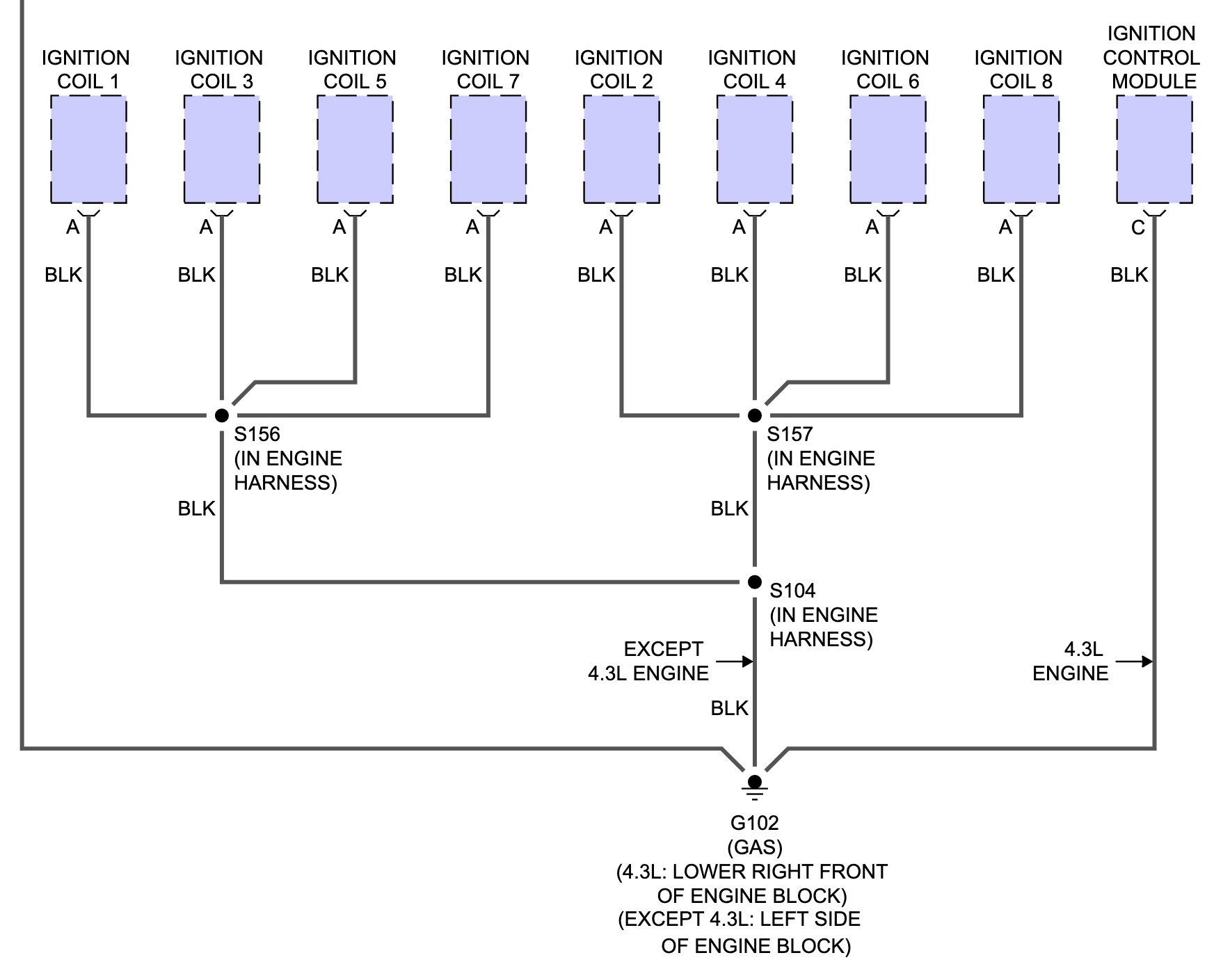
I went to the wiring diagrams next, and it turns out that the coils all grounded at G102 on the lower left of the engine block. I thought there may be something else that utilized the same ground, which could explain the strange back-feed that caused the fuel pump relay to engage, but nothing else did. It was a sole ground for the ignition coils.
I’ve gone down strange back-feeding rabbit holes before and gotten nowhere, and from where I was along the line of diagnosis, I knew there was also a low-reference and signal circuit on each coil, and I thought it very possible that some type of back-feeding was occurring in one of these circuits. I felt confident that the problem was just a bad ground, but I wanted to check a couple more things.
I decided to open the wiring harnesses along the top of the engine to follow the ground wire from each bank of coils. They came together in a splice, then a single ground wire branched from the main harness and ran down the front of the block along with a few other wires, until it exited to bolt to the engine block.
I cut the ground wire after the splice and checked the continuity of the coil grounds from each bank up through the splice and the wires were good. Then, I checked continuity of the ground wire leading down the block and, as suspected, it had extremely high resistance. I had found the problem.
Since I was eager to cement this one and hear it run, I connected a jumper between the splice and the negative battery terminal and hit the key. It fired right up without hesitation and was smooth as silk.
I always say to stick to the flow chart for any diagnosis. I was guilty of going my own direction at first, partly because I wanted to learn a little about the system, but also when you have something that’s been worked on before, your starting point can get thrown off.
I always rethink my process when I’m done to determine if I should have done something (or everything) differently, but I was happy with the way it turned out. I learned a bit; I didn’t guess at anything and I didn’t throw any parts at it. I just made money for my time, and that’s the name of the game.
After repairing the bad ground, I reinstalled the bolt for the CMP sensor hold-down, replaced the broken oil pressure sending unit and sealed up the wiring harness. During all this I found the starter solenoid connection was loose, so I tightened it up and oh, yeah, I also found the blue-handled pry bar.