By Daniel Skinner
Occasionally in diagnosing transmission problems, technicians are faced with challenges that force us to look beyond the transmission control system. As vehicles become increasingly complex, it is crucial that we educate ourselves with all systems pertaining to the vehicle we are diagnosing. Many systems are tied together in one way or another and can directly affect performance and function across those systems if a malfunction is present in one of them.
It is also very important that we invest in more than one source of technical information. All too often I have encountered discrepancies in the information I have found while diagnosing a problem. It is up to us to be able to recognize incorrect and/or incomplete information that we are accessing. In many cases this can be time consuming but is a necessary part of our jobs. As vehicle manufacturers add more and more systems and integration, the importance of correct and complete information becomes even more important.
One example that I encountered was on a 2016 Ford F-150 4×4 equipped with 5.0L engine and 6R80 transmission. The truck was towed to our shop and the customer stated that it would not start. The customer was told by another shop that it was not showing proper gear selection. This prompted him to bring it to us, as it appeared to be transmission related.
Upon my initial evaluation, I found there to be a “no crank” condition. The range indicator in the cluster showed no selected range no matter what position the shifter was in. Four codes were stored in the PCM: P0706 (Range Sensor “A” Circuit Range/Performance), P0707 (Range Sensor “A” Circuit Low), P1702 (Range Sensor Circuit Intermittent) and P1921 (Range Sensor Signal). When those codes were cleared, they immediately returned when the key was cycled off and back on indicating that I had a hard fault. My immediate suspicion was a failed TRS (transmission range sensor), which is an integrated part of the molded lead frame inside the transmission. This is where digging a little deeper and educating yourself becomes crucial.
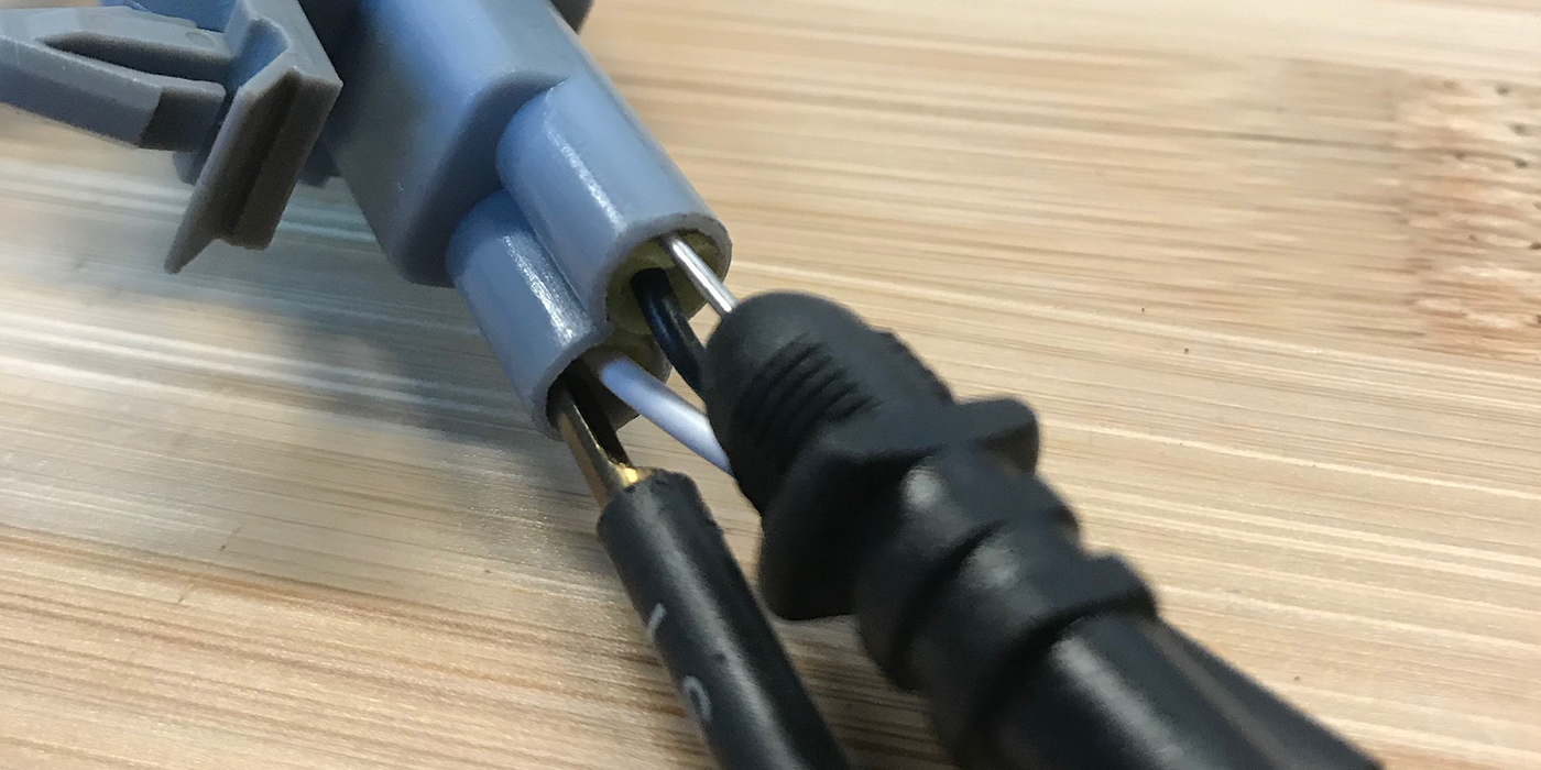
I needed to prove that the range sensor was faulty. I began by checking for voltage (VPWR) to the transmission range sensor. This voltage is supplied by the PCM and should be at or near battery voltage. I back-probed circuit LE111 (violet/green wire) at the transmission connector. To my surprise I found only 1.9V present. See Figure 1.
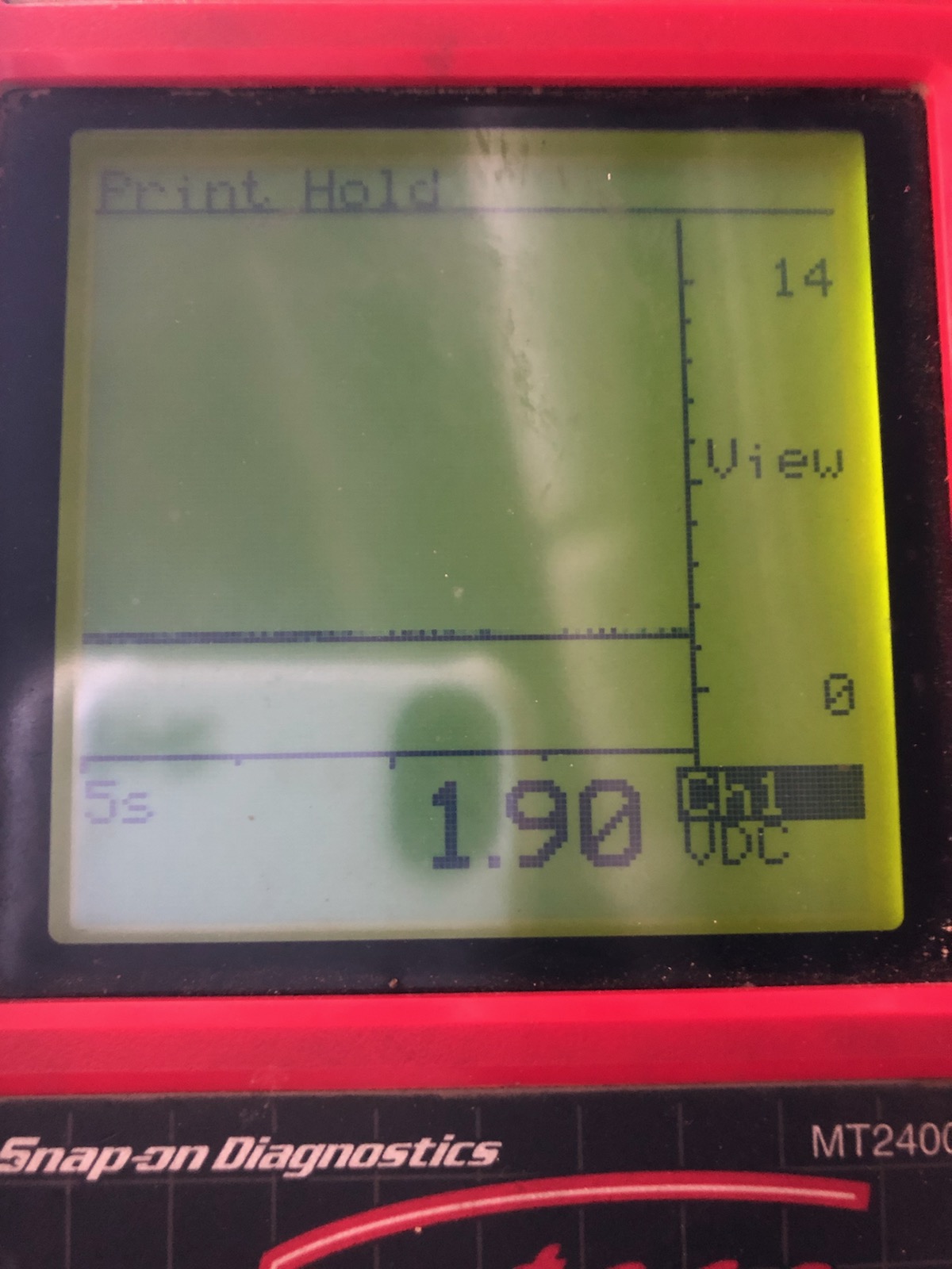
Did I have a lead frame problem causing voltage to be low? I disconnected the transmission connector to take the lead frame out of the equation, thinking it would change. That was not the case; I still had only 1.9V on circuit LE111. Could there be a wiring problem between the PCM and transmission connector? Possibly a pinched or frayed/damaged wire? At this point I back-probed the same violet and green wire in connector C1381E at the PCM. I found that there was only 1.9V on the circuit at that location as well. With the TRS out of the circuit, I now suspect the PCM is failing to provide the correct voltage to circuit LE111.
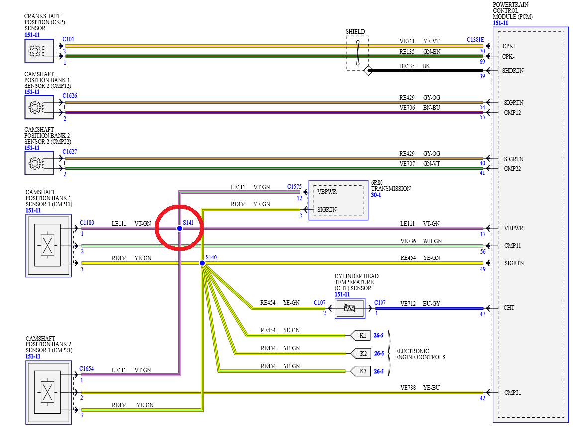
Before replacing the PCM I decided to review the manufacturer’s wiring diagram one more time. On the transmission controls wiring diagram, I nearly overlooked an important detail. On circuit LE111 there is a splice (S141). See Figure 2.
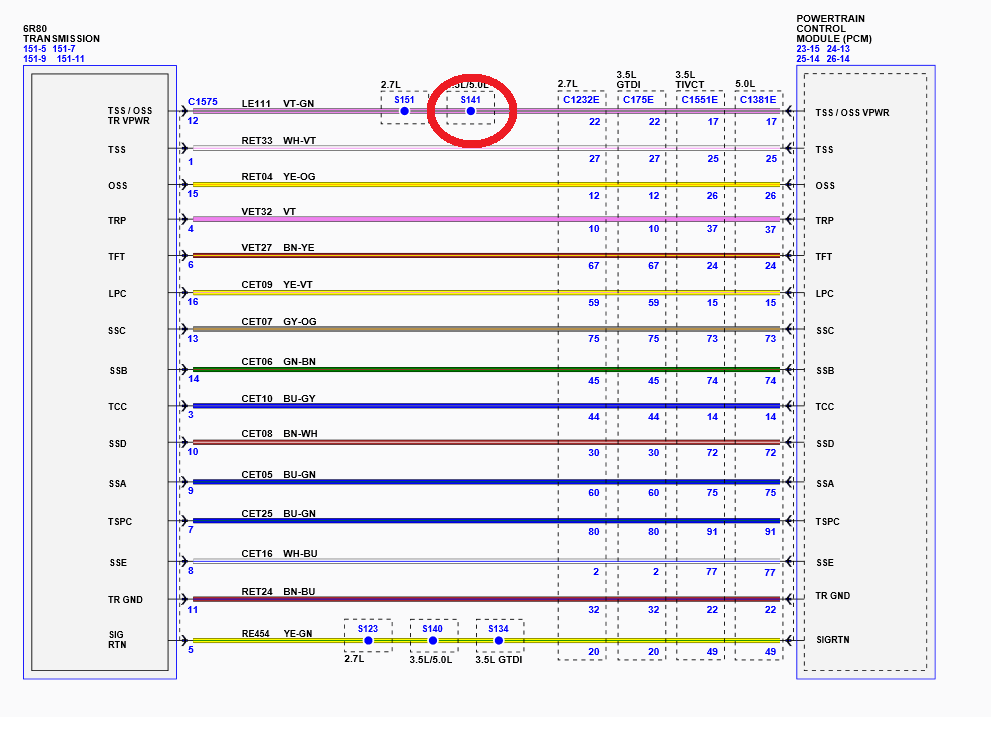
The diagram shows a splice, but no other wires were shown coming out of that splice. Since the very purpose of a splice is to distribute a circuit to other components, this did not make any sense. After over an hour of searching for more information on S141, I finally found another third-party wiring diagram with more detail about it. The diagram I found pertained to the electronic engine controls for the 5.0L. In that diagram I discovered the reason there is a splice in the circuit! S141 distributes voltage not only to the TRS, but also to the camshaft position sensors! See Figure 3.
The 5.0L engine utilizes two camshaft position sensors; they are located at the rear of each cylinder head, near the firewall. Could there be a faulty sensor or damaged wire bringing down the supply voltage provided by the PCM?
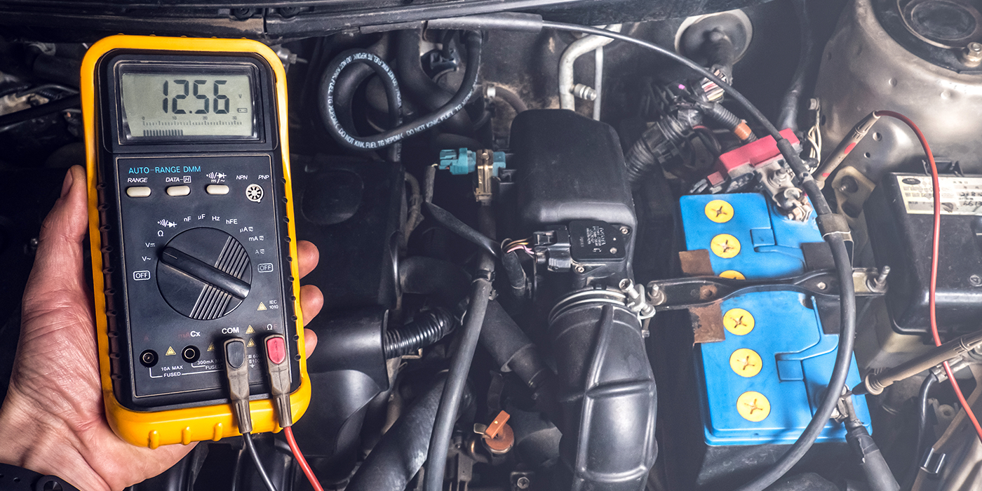
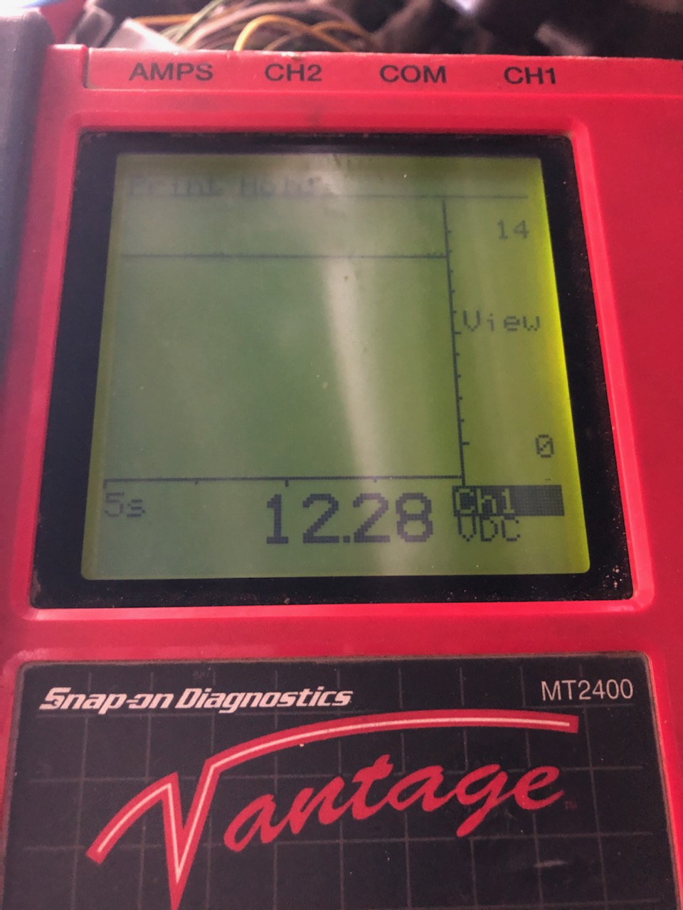
My next move was to once again back-probe circuit LE111 at the PCM. While back-probing with the key in the “on” position, I disconnected the left bank camshaft position sensor. That resulted in no change of voltage on the circuit. I then disconnected the right bank camshaft position sensor, and bingo! Voltage on circuit LE111 immediately jumped up to 12.28V. See Figure 4.
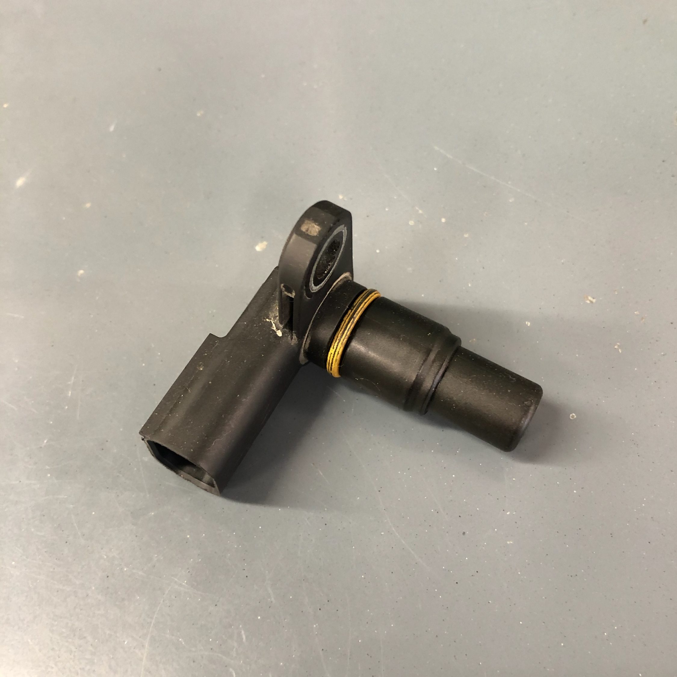
I had finally found the culprit: an internally shorted camshaft position sensor. See Figure 5.
After replacing the faulty sensor and clearing the codes, the truck started and worked perfectly.
Keep in mind that there were no driveability complaints prior to the no crank condition, nor any other codes that might pertain to a problem with a camshaft position sensor.
The most frustrating part of this was the issue of not having the correct information. This is exactly why it is paramount that we have access to and use multiple resources for reference. If we rely on one source, be it manufacturer-provided information or not, sooner or later you will encounter a problem with the information provided. I have seen it with all sources. Had I relied on the initial wiring diagram, I would have never known that the camshaft position sensors were part of the circuit and probably replaced a part (or parts) that would not have resolved the problem. This would obviously cost unnecessary time and money.
Take the time to do the homework. Successful results and happy customers will follow. TS