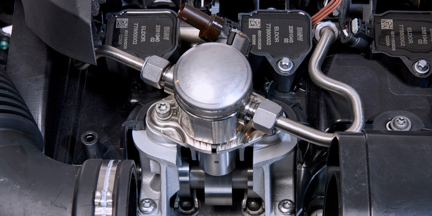
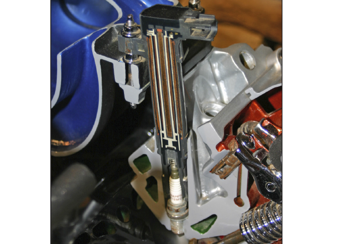
Kilovolts or kV is the unit used to measure the output of an ignition coil. Some coils can output 20kV to 40 kV. So, how does an ignition coil turn system or battery voltage into these huge voltages? The answer is inductance.
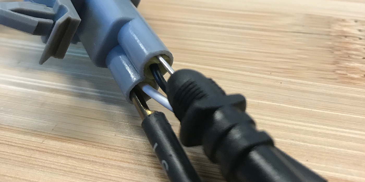
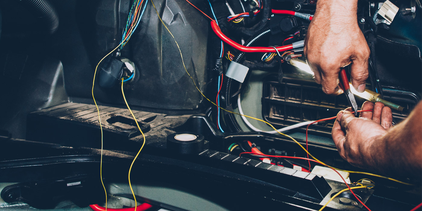
The ECM provides the voltage to the primary coil winding. The primary winding might have 100 turns around the coil’s core or plates. When the voltage to the coil is turned off, a magnetic field collapses. The collapsing field will generate more than 100 volts thanks to inductance. The energy is transformed by the windings in the secondary with inductance again, but thanks to the 10,000 windings, the voltage is boosted to 40kV at the spark plug’s electrodes. The best way to see inductance inside the primary windings is to use an amp probe placed around the positive wire for the ignition coil. With this setup, you can see the current ramping in the coil and the collapse of the magnetic field.
If you look at a secondary ignition waveform on a scope, you will see a spike representing the coil’s output. I know what you are thinking: if the ignition coil has a fixed ratio of primary and secondary windings, and the system voltage is constant, shouldn’t the spike be the same all the time? In theory, yes. In practice, the spark plug and mixture of air and fuel inside the cylinder can determine how high the spike will go on your scope.
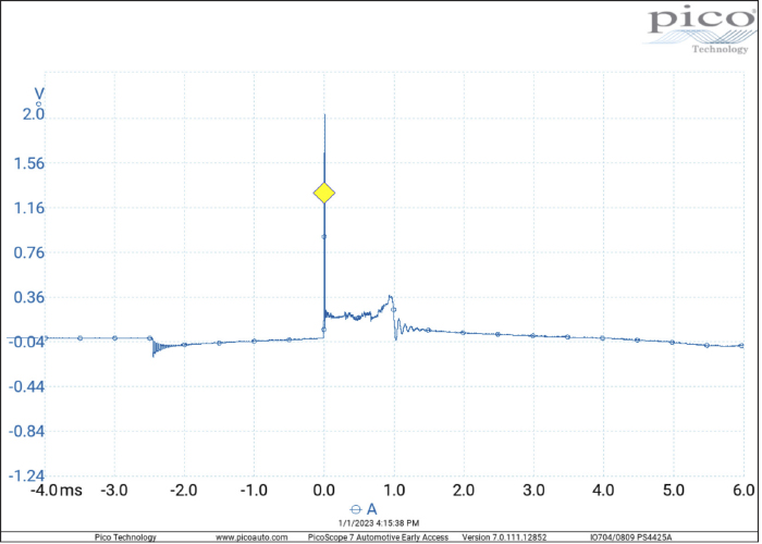
The spike is when the coil discharges, and the spark jumps from one electrode to the other. This spike changes depending on the resistance between the center and side electrodes. The resistance depends on what is going on inside the combustion chamber.
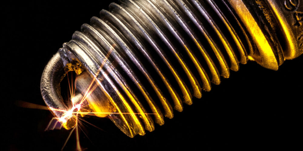
Imagine the air and fuel inside the combustion chamber as electrical resistors between the spark plug electrodes. If you increase the distance between the electrodes, you increase the amount of air between the electrodes and the value of the resistor between them.
As cylinder pressure rises and the fuel mixture changes, the amount of energy required to fire the plugs also increases. This is why the spike should increase in height if you snap the throttle.
If the spike does not increase when the throttle is snapped or is lower when compared to the other coils, it is a sign the spark might be escaping to areas other than the spark plug electrodes. This could be caused by a shorted connector or boot with an air gap. It could also be the case that the windings inside the coil are damaged.
To the right of the spike is what is called the “burn” or “spark line.” This lower part of the secondary ignition waveform represents the when the plasma is present between the two electrodes. As the energy in the secondary windings dissipates, the line should gently slope downward. Some spark lines might change in shape as the resistance changes between the electrodes inside the cylinder. This change in resistance could be caused by turbulent air or droplets of fuel passing between the electrodes.
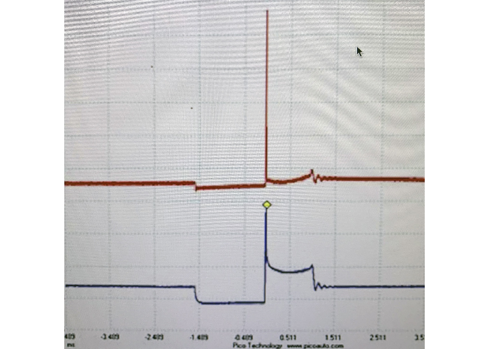
When there isn’t enough energy in the secondary windings, the spark line drops to the zero line. Depending on coil design you might see oscillations in the waveform.
The key with the spike and spark line is to compare it to the other coils on the vehicle. If one spike goes higher than the rest, it signifies two things. First, the resistance in the combustion chamber could be different than the rest of the cylinders, or the spark plug could be worn. If the spike is significantly lower than the rest of the cylinders, it is a sign that the resistance is lower in the plug or cylinder. Sometimes, a clogged or dead fuel injector can cause a lower spike when the throttle is snapped.