 By Oleg Malin, Vasyl Postolovskyi & Olle Gladso
Contributing Writers and Instructors at Riverland Technical and Community College in Albert Lea, MN
Recently, a Volkswagen Turbo Diesel was towed in as a no-start. The owner of this vehicle had called a while ago and complained about an intermittent loss of power while driving, but did not have time to come in for diagnostic work. But now, the vehicle stalled while he was driving it and it would not restart.
Scanning the vehicle revealed several codes, but no direct “smoking gun.” Table 1 lists the trouble codes stored and obtained.
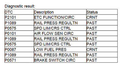
DTC P0087 indicates that there is no pressure in the fuel rail. After priming the system, fuel pressure did appear, however, the engine would still not start. It sounded like it was trying, but would not fully run.
The protective cover over the injectors was removed; this also involved removing the tubing going to the turbo, due to interference with the cover. Trying again, the engine actually started, but ran very poorly. Exhaust was being expelled from the intake system. The oil filler cap was removed, revealing smoke and engine oil being ejected from the opening. The excessive amount of blowby was indicative of a cylinder leakage from, for example a piston with broken piston rings or a piston with a hole in it. Time to check for a compression issue.
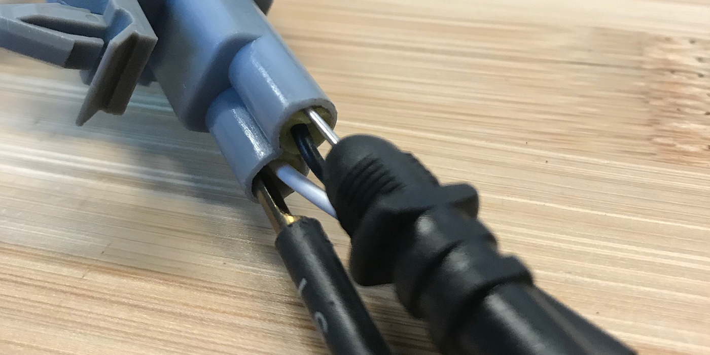
A USB Autoscope was used to look at relative compression using an amp clamp. The amp clamp was attached around the negative battery cable and an injector simulator was connected to the harness connector for the number 1 cylinder injector while the rest of the injectors were left disconnected. (The injector simulator is simply a piezo element salvaged from a similar diesel fuel injector.) Another amp clamp was attached to one of the wires going to injector connector for cylinder 1. The signal from this amp clamp was used to synchronize cranking current waveform to specific cylinders.
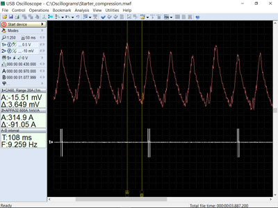
Figure 1 shows the cranking waveform obtained using the setup described.
The relative compression waveform did not reveal anything out of the ordinary. The delta current or compression peak current was about 90 A. Cylinder number 2 had a slightly higher delta than the others, all the rest were about the same. But what was the cause of exhaust being blown back out of the intake?
Since it is fairly easy to get to the glow plugs on this particular engine, it was decided to check absolute compression. The px35 pressure sensor from the Autoscope kit was used for this task as shown in Figure 2.
The following measurement results were obtained:
Cylinder number 1: 21.7 Bar (319 psi).
Cylinder number 2: 22.8 Bar (335 psi).
Cylinder number 3: 21.8 Bar (320 psi).
Cylinder number 4: 21.5 Bar (316 psi).
When taking into account the added volume from the extension used with the pressure transducer, the compression readings were normal, with cylinder number 2 being slightly higher. This was the same result as what was obtained using the relative compression test earlier.
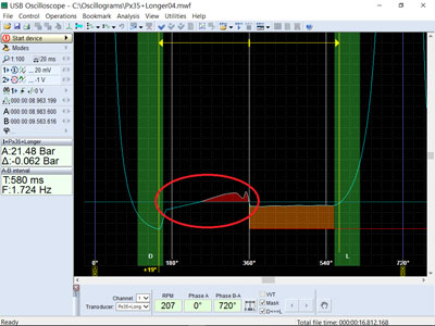
Since the Autoscope was used along with the pressure transducer, we now had cylinder pressure waveforms. Cylinder pressure waveforms can reveal much more information than just cylinder pressures. Figure 3 shows the cylinder pressure waveform taken from one of the cylinders.
The circled area in Figure 3 shows an incline, which indicates an increase in cylinder pressure on the cylinder’s exhaust stroke. This is not normally observed on a diesel engine. That area of the waveform should be flat or horizontal.
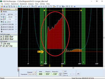
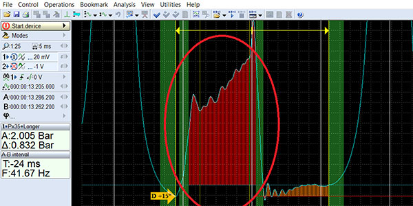
To test further, the pressure transducer was left in the fourth cylinder, the other three injectors were reconnected, the engine was started and allowed to idle. The cylinder pressure waveform was then recorded. Figure 4 shows the resulting waveform.
The waveform shows that on the exhaust stroke there was a back pressure of about 2 Bars (29 psi)! This was at idle, so there was clearly a complete or almost complete blockage in the exhaust.
The turbo was removed and inspected. The turbine/compressor assembly was found to be completely seized, causing a severe exhaust blockage. The seized turbo is shown in Figure 5.
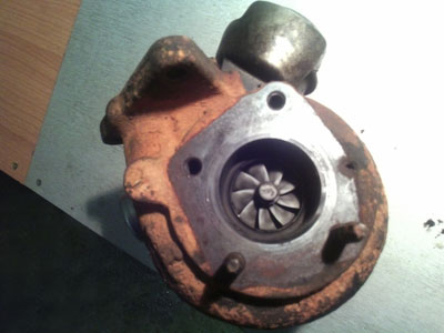
Since there is usually an underlying reason for this type of failure, the rest of the exhaust system was inspected and found to be partially plugged. The partial restriction caused excessive exhaust temperatures which, in turn, caused the turbo failure. The exhaust system was repaired and the turbo replaced. If the exhaust system had been left alone, the likely result would have been another turbo failure.