e to advance your diagnostic readiness by examining the VVT system, its controls and operation.
 Mechanical, hydraulic and electrical controls have been added to VVT engines.
Motor oil is the hydraulic medium that makes VVT work.
That means it is imperative that engines are filled to the correct level with clean motor oil of the proper viscosity.
Low oil level or the wrong viscosity can result in system slow response codes such as P000A or P000B and possible drive complaints including an illuminated MIL.
Oil pressure is critical, and as bearings wear and develop clearance, pressure will be affected.
 Engines are machined with additional oil galleys for VVT and are equipped with one or more fine mesh screens to prevent debris from entering components.
Replacing these screens often requires major engine disassembly.
Sensors that monitor oil pressure and oil temperature are common on VVT engines and are a part of system control strategy.
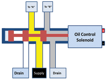
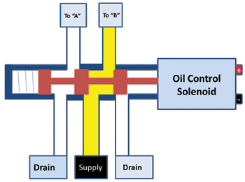
The major control component in camshaft phasing is the oil control valve (OCV). The OCV is a spool valve much like those found in automatic transmissions. The PCM (powertrain control module) duty-cycles a solenoid that alters valve position.
The OCV is an oil traffic control device of sorts. It determines which ports receive pressurized oil and which are vented.
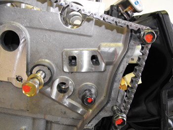
(See Figures 2, 3, 4 and 5.)
Pressurized oil travels through the OCV to one of the camshaft bearing journals. Oil flows though passageways inside and toward the front of the camshaft.
(See Figure 6.)
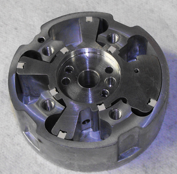
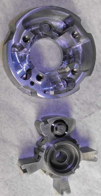
At the nose of the camshaft, oil enters ports of the camshaft phaser. The phaser is a mechanism with two major pieces, the rotor and the phaser body. 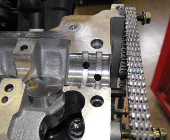
The phaser body is physically bolted to the camshaft sprocket. The rotor is connected to the camshaft using a dowel pin.
(See Figure 7.)
The two pieces are able to move about 20° (40 crankshaft degrees) independently of each other. Ports inside the phaser direct oil in or out of eight chambers.
Four chambers are considered side “A” and the other four are side “B.”
As one group of chambers receives pressurized oil, the others are vented to provide the force necessary to move or hold the rotor relative to the phaser body.
 Oil seals fit into machined grooves of the rotor to provide a tight seal between the chambers.
Vented oil from the phaser ports travels back through the camshaft, the cam bearing ports, through the oil control valve and then drains into the front timing cover.
There is a mechanical device inside the phaser known as a lock pin.
The spring-loaded lock pin on the rotor engages into the phaser body to lock the two pieces together.
(See Figure 8.)
The lock pin prevents noise and potential wear upon engine start. Oil pressure is required to disengage the lock pin.
The 2.4L Chrysler engine that I disassembled also featured a spring on the exhaust camshaft.
 The locked phaser positions on this engine are full retard on the intake and full advance on the exhaust.
Because of the clockwise rotation when viewed from the front of the engine, the exhaust rotor requires additional assistance in reaching the full advance position.
In the default position, there is no valve overlap. It should be noted that service information does not recommend phaser disassembly and individual parts are unavailable.
As for service parts, phasers are sold as an assembly.
Electrically, the OCV solenoid has two terminals. I measured the resistance of several solenoids from various manufacturers.
They ranged between 7 and 12 ohms of resistance.
Both circuits connect to the PCM, which provides duty-cycle control either on ground or the insulated (power) side.
I found versions of both on our laboratory vehicles. OCV solenoids are typically cycled upon ignition run mode as part of a cleaning and diagnostic strategy.
Regardless of control specifics, the PCM monitors solenoid circuits for faults including opens, shorts to ground or shorts to voltage.
(See Figure 9.)
OCV solenoid circuit faults include P0010 and P0013.
We recently had a late-model V6 minivan in our lab with one of these codes.
 The solenoid was internally leaking a small amount of oil, just enough to soak the electrical connector.
Electrical contact cleaner and a new OCV solenoid repaired the vehicle.
These faults are on board diagnostic comprehensive components rather than once-per-trip monitors.
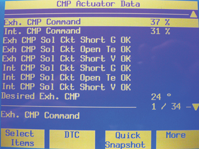
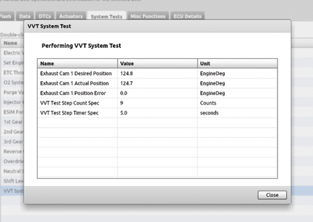
Besides retrieving trouble codes, scan tools are useful to monitor desired versus actual camshaft position and may also be equipped with helpful actuator tests and cleaning routines.
(See Figure 10.)
Crankshaft position sensors (CKP) and camshaft position sensors (CMP) are used by the PCM to determine camshaft phasing functionality. CMP tone rings or trigger wheels are usually connected to the cam itself rather than the cam sprocket.
When the PCM commands the OCV solenoid to advance or retard, CMP patterns are compared to CKP patterns to determine if the command is carried out.
A variance or error value is calculated. Once the variance reaches a certain point, a fault is declared. These include DTCs P0011 and P0014, which are target performance errors.
This also makes it more important than ever that camshaft timing be set correctly during timing chain or belt service.
A CKP or CMP sensor fault can also cause the PCM to disable or limit VVT operation.
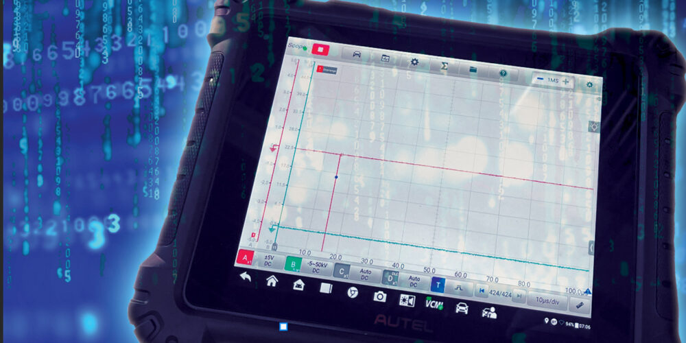
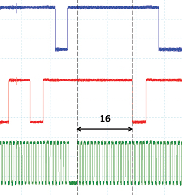
I tested a 2006 Pontiac Solstice equipped with the dual VVT EcoTech engine using a duty-cycle test box to command the OCV solenoids. 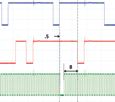
By comparing CKP and CMP patterns with the solenoids fully on then fully off, I determined about 48 crankshaft degrees of possible cam travel.
(See Figures 11-13.)
When the exhaust was commanded to the full retard position at idle, the engine ran rough and manifold vacuum dropped below 15” of mercury.
When I manually commanded the intake to full advance, manifold vacuum dropped only 2” and the engine started to sound like a diesel.
The vehicle was restored to proper operation and driven on a dynamometer to get a glimpse into VVT control strategy.
At idle and during deceleration, the OCV solenoids remained off, resulting in the default position of fully retarded intake and fully advanced exhaust.
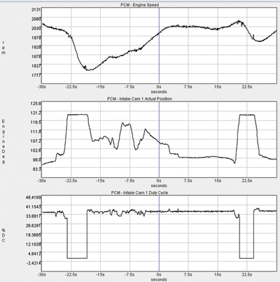
 The wide lobe separation angle with no overlap is ideal for smooth idle. I also performed on-road data recordings on a 2012 Dodge Avenger equipped with a 2.4L dual VVT engine similar like that which I had disassembled.
Like the Pontiac, the Dodge also maintained a 0% duty cycle at idle and deceleration.
While testing these vehicles, the exhaust OCV solenoid is quick to activate while the intake OCV solenoid seems more sensitive to engine load.
I observed the most movement on both cams during cruise. The solenoids on both vehicles were duty-cycled moving the intake near full advance and the exhaust near full retard.
(See Figure 14.)
This reduces lobe separation angle and results in a large amount of valve overlap. This appears to be done to eliminate the EGR (exhaust gas recirculation) valve.
None of our many lab vehicles with phaser-style VVT have an EGR valve. Overlap at cruising speed is used to dilute the intake charge. 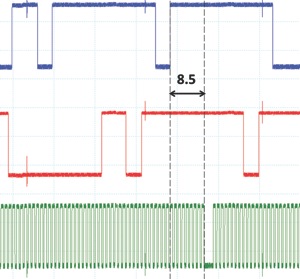
Spent exhaust takes up space in the cylinder and results in less oxygen content per charge, meaning less fuel is necessary.
Combustion chamber temperature is reduced to lower oxides of nitrogen (NOx) emissions.
Fuel economy is also improved.
Recordings were also performed at wide open throttle (WOT).
With manifold pressure near atmospheric pressure or vacuum held close to zero, I wanted to see the influence of rpm build on the cams.
On the Avenger, the intake cam is the one with more correlation with rpm.
(See Figure 15.)
The intake cam starts out with large amounts of advance for increased low-end torque, but it gradually moves toward the full retard position once rpms build to about 5,000.
This seems to make theoretical sense with increased inertia of the intake charge able to keep air flowing into the cylinders even as the pistons start moving up on the compression stroke.
The exhaust cam seems to hold steady at about one-third of the way toward full retard.
This provides a balance between performance and emissions.
There are most likely other control strategies on these and other manufacturers’ vehicles.
With vehicle manufacturers having to use every tool at their disposal to meet sharply increasing CAFE (corporate average fuel economy) requirements, it is likely we will see more VVT-equipped engines. 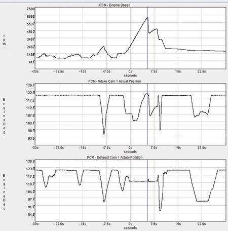
These systems are well engineered and have proven to be reliable.
That being said, heat, age, wear and lack of maintenance are likely reasons to cause eventual failures.
Looking at these components, including the fine mesh screens, provides great incentive to keep oil changed regularly.
Hopefully this look at the system components, controls and operation leaves you ready in time to service the growing number of VVT-equipped vehicles.