
The 2004-2013 GM W-Platform represents the evolution of the GM mid/full-sized front-wheel-drive car. The W-Platform includes best sellers like the 2004-2013 Chevy Impala, 2006-2007 Chevy Monte Carlo, 2004-2008 Pontiac Grand Prix and 2005-2009 Buick LaCrosse. This is a “bread and butter” vehicle for every shop. This generation of vehicles is solid and easy to work on. Gone are the quirks of previous generations.
We will be concentrating on the civilian V6-equipped version that represents about 95 percent of the W-Platform vehicles on the road. The V8 and Police versions have different alignment/ride height specifications and components.
The most important part of the alignment process is the customer interview. Find out why they need an alignment. Ask them if they are experiencing any clunks, thumps or pops. Also, ask at what speeds they are experiencing the problem.
Pre-Alignment Inspection
The 2006-current Impala has been for the most part trouble free, but the steering system, including the linkage and power assist system, has been the topic of several TSBs. If the rack has been replaced or there is a customer complaint of noise or clunks, take the time to check the TSBs for proper diagnostic procedures.
The first items to inspect are the tires. Make sure to match the tire pressures that are listed on the driver’s side door pillar. Inspect the overall condition of the tires. If the customer is complaining the vehicle is pulling, take the time to mark the original position of the tires before rotation or radial force measurement procedures.
It has been reported by several law enforcement agencies and bearing manufacturers that the stock front-wheel bearings have a limited life if the driver is aggressive. Make sure to inspect the bearings before you perform an alignment.
Always check the upper strut mounts. Visually inspect the upper mounts for play in the bearing and look at the condition on the rubber on the mount. Worn rear strut mounts can make a knocking noise. Check the steering rack bushings for play and wear. These bushings attach the rack to the engine cradle and will cause noise and steering feedback if worn.
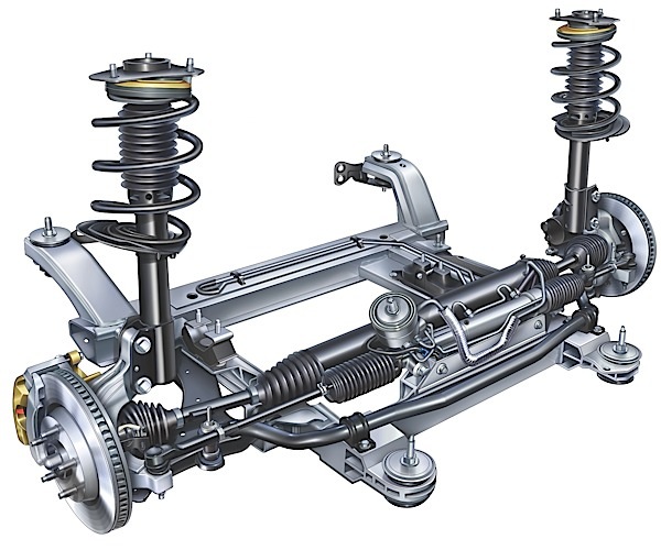
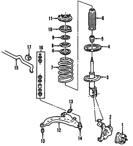
Front Suspension
Adjusting the camber requires some extra work. GM did not elongate the lower bolt holes that attach the strut to the knuckle on some vehicles or build adjustability into the upper strut mount. The 2010 documentation shows movement without requiring slotting.
Before performing the alignment, inspect any vehicle to find out if the alignment angles are adjustable or require extra parts, special procedures or kits.
If you rationalize that you can “eat” the extra labor time to slot struts or to install cam bolts in hopes that the next few alignments will be more profitable, you will be working for free more often than you think.
You can use two techniques to make the camber adjustable. First, you can file the lower bolt hole into a slot. GM recommends only performing this operation on the lower bolt hole. Typically, this can safely generate ±1.25º of camber adjustment.
Second, you can install a cam bolt in the upper strut-to-knuckle bolt hole. The aftermarket kits can give ±1.75º of adjustment. The strut-to-knuckle bolts should be tightened to 96 ft. lbs. Make sure the customer is charged for labor no matter what method is used.
There is no front caster adjustment on this vehicle. If the caster is out of specification, inspect the vehicle for damage to the lower control arm, bushings or the front crossmember.
Toe is adjusted with the tie rods. Make sure the bellows of the boot are aligned and the boot is in good condition. It has been reported that if the boot is misaligned or sagging, it can get caught on the inner tie rod and bind up or cause a popping noise.
There are no special procedures to recalibrate the steering position sensor after the vehicle has been aligned. The calibration is performed by the computer when the vehicle is first driven.
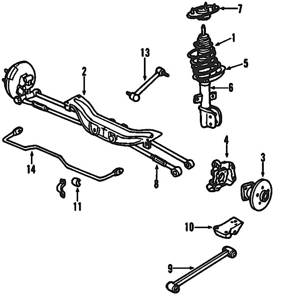
Rear Suspension
The procedure to adjust the rear camber is to install cam bolts in the upper hole slots. The torque spec for the bolts is 89 ft. lbs. The toe is adjusted with the rear adjustable lateral link.
Check the bushings on the lateral links. When the bushings wear, the tires will show an inner edge wear.
TSB Checks
01-02-32-001P (Clunk While Turning): Some customers may comment on a clunk-type noise coming from the front of the vehicle while driving during a turning maneuver. This condition may also be felt through the steering wheel when the vehicle is stationary and the wheel is rotated from steering stop to steering stop.
Some vehicles may only exhibit the noise once for every 360° of wheel rotation. On all other vehicles, this clunk noise will be noticed during low speed acceleration or deceleration, typically in light turns of the steering wheel or when applying/releasing the brakes. This condition may be caused by a “slip stick” condition of the steering intermediate shaft resulting in the clunk noise or feel through the steering wheel. GM recommends replacing the shaft with an updated part.
07-03-09-001J (Creak, Pop, Clunk Noise, Rear Strut, Upper Mount): Some customers may comment on a creak, pop or clunk noise coming from the rear of the vehicle. This condition may be caused by the rear strut spring rubber isolator contacting the lower spring coil. Through the rear wheelhouse opening, locate the lower first four rubber isolator tabs. Using a utility knife, cut the four tabs flush with the surface of the isolator. Be careful not to cut all the way through the rubber isolator to the metal spring coil. Apply a high-temperature water-resistant grease to the lower spring coil. Cover the entire area under the removed tabs.
INDIRECT TPMS
Some 2004-2007 W-Platform models use indirect tire pressure monitoring systems that use the wheel speed sensors to determine inflation. The software requires up to 8 km (5 miles) of straight line, smooth road driving in each of the four speed ranges to complete the calibration process in order to have any capability for detecting a tire pressure condition.
19 – 40 mph
40 – 59 mph
59 – 74.5 mph
74.5 – 90 mph
Each of the speed ranges have 2 modes of operation:
• Calibration
• Detection
In calibration mode the TPM system is learning the tire pressure calibrations and can not detect a low tire pressure condition. In detection mode the TPM system has learned the tire pressure calibration and can detect a low tire pressure condition. If the pressure in one tire becomes 7-10 psi lower or higher than the other three, the EBCM commands the DIC to display The LOW TIRE PRESSURE warning message.
Important: After resetting, the TPM system requires up to 8 km/h (5 miles) of flat, smooth road straight line driving in each of the four speed ranges to complete the calibration process.
Using the Driver Information Center (DIC)
1. Set all tire pressures to the recommended kPa/psi (refer to Tire Inflation Pressure Specifications).
2. Turn ON the ignition, with the engine OFF.
3. Press the vehicle information button until TIRE INFLATION MONITOR SYSTEM PRESS (down/left arrow) SWITCH TO RESET is displayed.
4. Press and hold the down/left arrow button until TIRE INFLATION MONITOR SYSTEM HAS BEEN RESET is displayed.
5. Release the down/left arrow button and TIRE PRESSURE NORMAL is displayed.
Direct TPMS
TPMS Sensor Matching
1. Set the parking brake.
2. Turn the ignition switch to ON/RUN with the engine off.
3. Press and hold the keyless entry fob transmitter’s LOCK and UNLOCK buttons, at the same time, for about five seconds to start the TPMS learn mode. The horn sounds twice indicating the TPMS receiver is ready and in learn mode.
4. Starting with the left front tire, activate the sensor by holding the TPMS tool aimed upward against the tire sidewall close to the wheel rim at the valve stem location. Press and release the activate button and wait for a horn chirp.
5. Once the horn chirp has sounded, the sensor information is learned and the turn signal in the next location to be learned will illuminate. On most models, the driver-side front turn signal also comes on to indicate that corner’s sensor is ready to be learned.
6. When a sensor ID has been learned, the module sends a serial data message to the BCM to sound a horn chirp. This verifies the sensor has transmitted its ID and has received and learned it. The module must learn the sensor IDs in the proper sequence to determine sensor’s location.
The first learned ID is assigned to the left front location, the second to right front, the third to right rear and the fourth to left rear. On most models, the turn signals will individually illuminate indicating which location is to be learned in the proper sequence.