By Oleg Malin, Vasyl Postolovskyi and Olle Gladso
Contributing Writers and Instructors at Riverland Technical and Community College in Albert Lea, MN
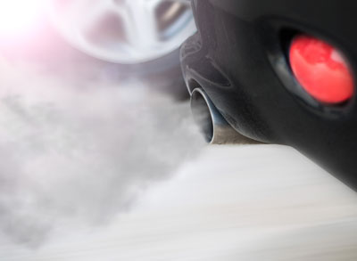
The vehicle in this month’s Maximizing Tools is a Nissan that was towed into our shop as a no-start. The engine stalled while driving and would not restart. This particular vehicle uses an engine from Renault, the 1.5dCi K9K. It uses a Siemens fuel system, but not diesel particulate filter on the base model. The engine does use a catalytic converter.
Scanning the vehicle revealed diagnostic trouble codes (DTCs) as listed in Table 1.
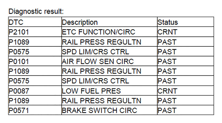
DTC P0087 indicates that there is no pressure in the fuel rail. After priming the fuel system, pressure did appear, but the engine still doesn’t start — it acts like it’s trying, but is not quite making it.
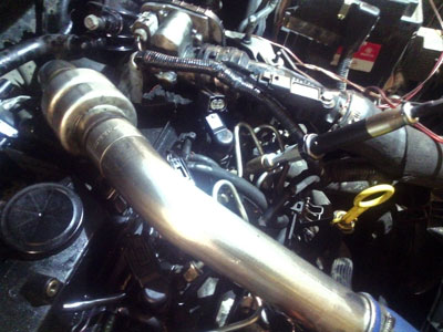
I remove the protective cover over the injectors. Because the pipe from the turbo to the intake is in the way, I remove it as well. Now the engine starts! However, the engine is not running well and exhaust is being expelled from the intake. I remove the oil filler cap to find that there is pressure in the crankcase. Oil and smoke are coming from the opening for the oil filler cap. Normally this indicates a piston with a hole in it or broken piston rings at the very least. I go ahead and test for that.
I connect my USB Autoscope III to test the relative compression using a current transducer. To perform the test, I clamp my current transducer (an APPA32 high amp transducer) around the negative battery cable. I then disconnect the injectors and connect an injector simulator to the connector for injector No. 1. The simulator is a piezoelectric element removed from a faulty injector. A second current transducer (A CA60 low amp transducer) is clamped around one of the injector wires going to the simulator. The signal from this transducer is used for synchronization.
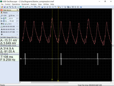
According to Figure 1 there is not much wrong with the relative compression. The current increase, or delta, is about 90A when the pistons are coming up on compression. There is a slightly larger delta in cylinder No. 2, but not very significant. The other cylinders are similar to each other. However, why is the engine experiencing a backflow of exhaust gases? Since the glow plugs are easy to access on this engine, I decide to perform an absolute compression pressure test as well. For this test I use a pressure sensor (the PX35).
Figure 2 shows the pressure sensor attached in place of a glow plug.
The results are as follows:
Cylinder No. 1: 21.7 Bar (314.65 psi)
Cylinder No. 2: 22.8 Bar (330.6 psi)
Cylinder No. 3: 21.8 Bar (316.1 psi)
Cylinder No. 4: 21.5 Bar (311.75 psi)
When taking into account the slight pressure loss from using an extension on the transducer, the compression is normal. Cylinder No. 2 has slightly more pressure compared to the others. This confirms the results from the relative compression test.
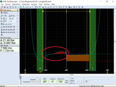
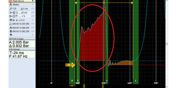
Figure 3 is the pressure waveform from one of the cylinders and there is an anomaly that warrants further investigation.
The inclined line on the exhaust stroke on a typical diesel engine is normally not seen — the line should be horizontal. The incline suggests a pressure rise in the cylinder on the exhaust stroke.
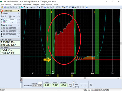
Figure 4 shows the pressure waveform in a cylinder at idle. To obtain this waveform, I restored the injector connections for three of the cylinders and left the pressure transducer in the fourth cylinder.
The waveform clearly shows a significant exhaust backpressure. There is about 2 Bar, or almost 30 psi, backpressure in the cylinder. The cylinders cannot expel the exhaust. The problem is most likely a literally completely blocked exhaust system. The customer had called a while back and complained about an intermittent loss of power, but didn’t have time to bring the vehicle in for us to diagnose the problem.
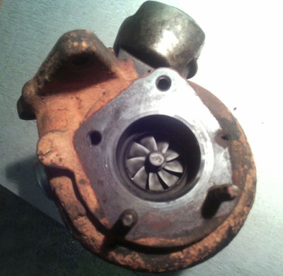
Figure 5 shows that the problem was caused by a failed turbocharger. The turbine had jammed and was blocking the exhaust. A new turbo was installed, but did not 100% cure the problem. The engine still seemed low on power, though, so another backpressure test was performed. The result indicated that there still was some backpressure present.
The catalytic converter was replaced and normal engine performance was restored.
Most likely, the partially clogged catalytic converter caused excessive exhaust temperatures, which in turn caused the turbocharger to fail. Always look for the root cause!