What diagnostic tool is most important? A scanner? An oscilloscope? At the end of the day, both are important, but by far the most important tool is using your head and to be able to think.
I say this with complete confidence. No equipment in existence can replace critical/logical thinking skills and the understanding of the various processes that take place in a modern vehicle. It, the vehicle, is a very complex piece of machinery incorporating mechanical, hydraulic, pneumatic, electrical and electronic devices and processes.
Relying on Diagnostic Trouble Codes (DTCs) for diagnostic purposes can, in many cases, only take you so far. Artificial intelligence notwithstanding, no known electronic unit has human intelligence. Our creativity can take us beyond the meaning and description of a DTC and enables us to find problems in those cases where a trouble code simply leads us down the wrong path and to a dead end.
So far, only humans can make connections and draw conclusions from seemingly disparate facts, enabling them to come up with answers and solutions to problems that seem, at least on the surface, illogical. Once that is said, we do unfortunately have to admit that not all automotive technicians are willing or able to spend the necessary time needed to develop the skills needed to arrive at a correct diagnosis if the problem present does not fit neatly into a pattern.
Many will simply read whatever trouble code is present and replace whatever part is indicated with no further thought given. This approach will often lead to large financial and/or reputational losses.
With the aforementioned facts in mind, here is an example. The vehicle is an Infiniti QX70, equipped with a V9X 3.0L turbo-diesel engine. The customer’s concern is that after a cold start, the All Wheel Drive (AWD) malfunction warning lamp comes on.
In a case like this, where a malfunction warning is indicated, the first tool to use is a scanner. We connect a Consult-III original equipment manufacturer scan tool and read the stored fault codes. It is important to keep in mind that DTCs will remain in memory for a predetermined time, depending on the relative importance of the actual system affected and whether or not the faults reoccur. So, codes may be related to a problem that no longer exists or is very random and/or rare in nature.
Take care so you do not go down a rabbit-hole chasing problems that may or may not actually exist. If in doubt, write down the codes, then erase them. Drive the vehicle like the owner normally would, then retest for DTCs. Any reoccurring codes are likely going to be valid and worth pursuing.
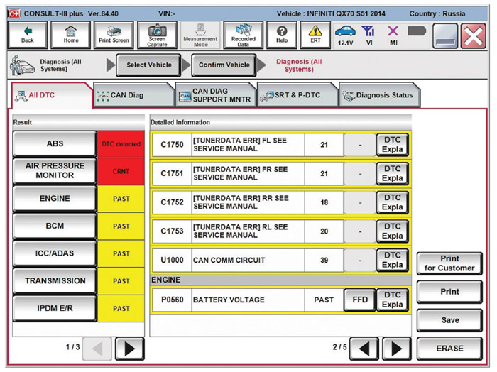
In this case, we read all the codes, and unfortunately there were codes in several of the vehicle systems. As evidenced in Figure 1, it is troubling to realize that many of the codes are related to the Controller Area Network (CAN) circuits. Not communication faults specifically, but circuit problems.
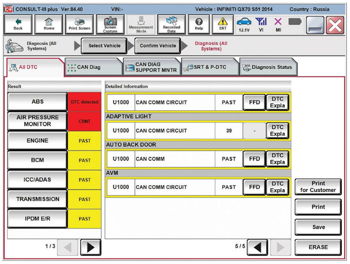
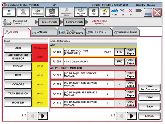
Many vehicle CAN bus circuits tend to experience glitches where codes for lost communication with one or more modules set for no readily discernible reasons. This was particularly true for early implementations; later model vehicles seem to have CAN buses that are more robust against these failures. On this particular vehicle, most modules flag CAN bus problems. That being the case, we can be reasonably confident that there is, in fact, a problem with the physical data bus. Figure 2 shows that the Engine Control Unit (ECU) has also set a DTC for system or battery voltage.
The ABS (Anti-lock Braking System) has set several codes as well. Of note is that, as Figure 3 shows, in addition to the CAN-related codes, there is a code for a battery voltage problem, just as in the ECU.
The correct voltage is one of the major requirements for electrical/electronic systems functioning properly. That being the case, it makes sense to solve the problem or problems with DTCs for battery voltage.
Although one could just test the voltage with a normal voltmeter, many prefer to test it using an engine analyzer or oscilloscope. A voltmeter will not reliably display short spikes and drop outs. Also, the actual shape of the voltage versus time graph or waveform can be difficult to discern with only a numeric display to review.
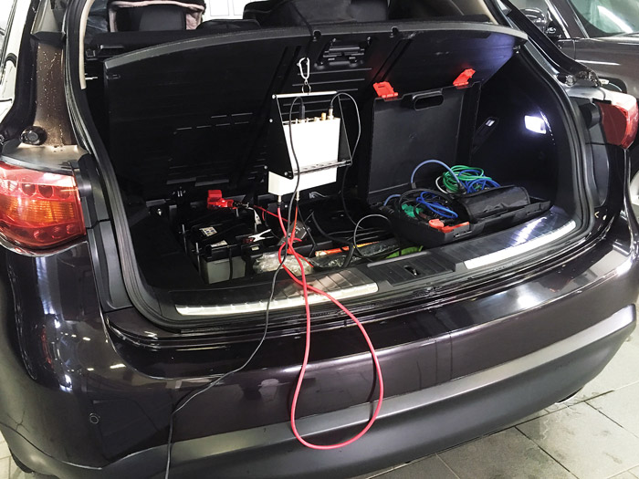
Unfortunately, many technicians do not spend the necessary time investigating problems with power supplies. In particular, intermittent problems with ground or power connections can be very difficult to catch if not specifically tested for. Some technicians have observed that, maybe especially on advanced vehicles such as this Infiniti, the amount of data available for display on scanners, even factory scanners, is being reduced. As seen in Figure 4 on page 18, the battery in this vehicle is in the trunk. We install our engine analyzer, the USB Autoscope IV, there.
We then proceed to run the relevant test. It is called the “ElPower” script and performs an automatic analysis of battery voltage and current waveforms. The script, in conjunction with the USB Autoscope IV, provides an advanced report on the battery, alternator and starter condition. The program will point to the problem areas.
We run the test. It is simple and takes only a couple of minutes. Figure 5 on page 19, is a display of the results, with the software highlighted in yellow parameters that do not fit into generally reasonable limits.
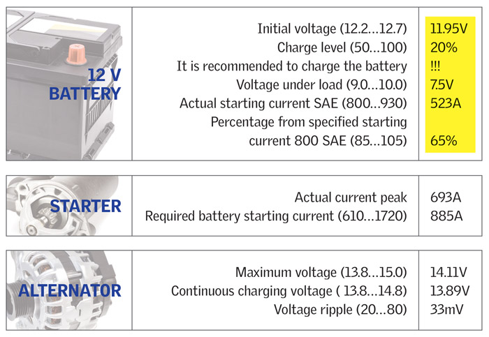
The initial voltage on the battery is only 11.95V. This means that the battery is deeply discharged (in fact, the script shows that the battery charge is only 20%). The recommendation to charge the battery is understandable, given the parameters shown.
The voltage during initial starter engagement and during peak current was only 7.5V. The voltage once the engine was rotating with a cranking current of 523A was measured to be 9.1V using the cursors on the oscilloscope screen. The initial voltage of 7.5V is too low for proper vehicle operation and likely causes module resets. A warm engine such as this one would cause the starter to consume less current than it would with a cold engine. A cold engine start, more than likely, would have shown even lower voltage.
Note that the software or script does not discern between voltage dips and sustained voltage. It only displays the lowest voltage recorded. A future update will cause the software to display both values.
It is very likely that during a cold start, the system voltage dropped sufficiently low that the CAN communication bus or the modules attached to the bus could not function properly. In this case, the ElPower script directly gave us the reason for the seemingly disparate CAN and module codes.
In conclusion: In many cases, do not solely rely on a scanner and DTCs; it may be the road to nowhere. A diagnosis should be based on an understanding of the processes that take place within the various vehicle systems.
After charging and testing, it became apparent that the battery was faulty, not just discharged. It was replaced and all problems, including the AWD malfunction lamp, were repaired.
Footnote: 9.1V during cranking is a very low system voltage. Too low for many vehicles/engines to reliably start. However, this particular engine is equipped with a common rail fuel system utilizing piezo injectors. The starting system uses a geared permanent magnet starter that will give acceptable cranking speed even with low battery voltage. The injector drivers are equipped with a voltage booster, which will boost the available voltage significantly since piezo injectors requires high drive voltage.