 By Omar Trinidad, assistant professor, automotive department, Southern Illinois University Carbondale
With the ability to increase fuel economy by up to 20% on gas vehicles and up to 40% on diesel vehicles, manufacturers have resorted to turbochargers to compensate for lowered engine displacement.
Additionally, the improvements on turbocharging technology have increased the number of turbocharged vehicles on American roads. Some turbocharger manufacturers have even projected the number of turbocharged vehicles in the U.S. to quadruple in the next five years.
To prepare technicians for the influx of the latest turbocharged vehicles, this article will cover the basic operation of the turbocharging system, electronically controlled wastegates and bypass valves, and feature a small segment on service/diagnostics.
 System Operation
Turbochargers provide a very efficient method for harnessing the wasted energy exhausted through the tailpipe. It is simply an exhaust-driven supercharger. The turbocharging system is driven by the basic concept of hot exhaust gases coming from the exhaust manifold driving a turbine wheel.
The rotation of the turbine wheel is then transferred by a shaft to a compressor wheel that forces air into the intake system.
It is important to understand that the turbocharger requires not just the flow of exhaust gases, but mainly the heat from the expanding exhaust gases, which produces the flow.
This explains why turbocharged engines do not produce maximum boost pressure when revved without any load.
Although the turbocharger can produce boost pressure from the flow of exhaust gases increasing as the engine is revved higher, under load, the temperature of the exhaust gases will be substantially higher and will be able to produce more energy to turn the turbine wheel. 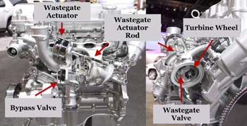
System Parts
Most original equipment (OE) turbocharging systems will have a turbocharger and an intercooler, and a way to control boost. Each part can be modified or upgraded using aftermarket parts. However, this article will focus more on OE applications.
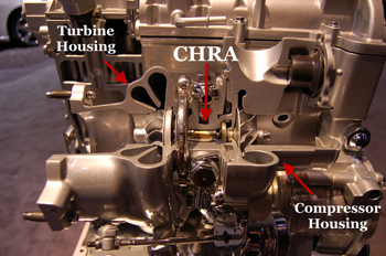
The turbocharger consists of three main sections: compressor housing, center housing rotating assembly (CHRA) and turbine housing (see Figure 1). The compressor housing, also known as the cold side, houses the compressor wheel and is attached to the CHRA and the intake plenum.
The CHRA section consists of the compressor wheel, turbine shaft, turbine wheel, bearings, and oil and coolant passageways. The CHRA is also referred to as the bearing housing. Lastly, the turbine housing, also known as the hot side, contains the turbine wheel and, on most applications, an integrated wastegate.
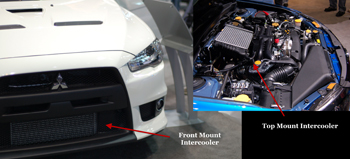
 Naturally, the temperature of the air will increase when compressed. Therefore, an intercooler is used to cool the air discharged from the compressor and increase power output. This radiator type component can be water-to-air, much like a radiator, or air-to-air where only ambient air passing over the fins cools the air passing through the intercooler.
There are several locations where the intercooler can be mounted: front-mount intercoolers (FMIC) are located in front of the radiator, top-mount intercoolers (TMIC) are located on top of the engine, and side-mount intercoolers are usually located inside the bumper (see Figure 2).
Although forcing more air into the cylinders increases the volumetric efficiency of the engine and desirably increases its power, there needs to be a way to control boost pressure.
 Since the turbocharger utilizes heat energy from the exhaust to produce boost and, more boost pressure produces more heat, a catastrophic chain reaction can occur if not controlled. Excessive boost can cause major turbo and engine damage.
Conversely, a deficiency in boost pressure will decrease the power output of the engine. Most systems utilize a wastegate and/or a bypass valve to control the system.
Wastegates are used to control boost pressure by redirecting the exhaust gases around the turbine wheel to bypass or maintain flow to the turbo. It utilizes a diaphragm attached to an actuator rod to open and close a valve.
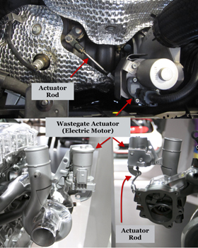
As shown in Figure 3, most OEM wastegates are integrated into the turbo, but some aftermarket applications utilize a remote design to enable the use of a larger diaphragm and better materials (see Figure 4).
 The wastegate is controlled by the amount of pressure the turbo is creating.
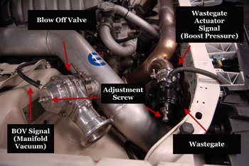
This pressure, usually derived from the intake manifold or compressor discharge, is referred to as the wastegate actuator signal. The valve opens once the wastegate actuator signal overcomes the diaphragm spring.
Most OEM systems will release the pressure back into the exhaust system for emissions purposes, but some performance vehicles release the pressure to the atmosphere.
While the wastegate protects the vehicle from producing too much boost, the bypass and pressure release valves, sometimes known as a blow off valve (BOV) or surge valve, are designed to release or displace boost pressure when the throttle is closed (Figure 3).
The unnecessary boost pressure is directed back into the compressor inlet after the mass air flow (MAF) sensor or out to the atmosphere. Directing the flow after the MAF prevents the system from running too rich when the throttle is abruptly closed.
Unlike the wastegate, both the bypass and pressure release valves are controlled by manifold vacuum. In addition, boost pressure assists in opening the valve by pushing while manifold vacuum pulls against the spring tension.
Although it does not increase the horsepower of the engine, some car enthusiasts install a BOV to make more noise because the excess pressure is expelled out to the atmosphere. Installing a low-quality BOV or modifying existing valves can cause damage to the turbocharger and/or decrease performance. 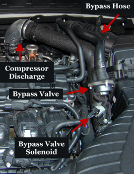
Electronically Controlled Wastegate and Bypass Valves
On late-model unmodified vehicles, the wastegate and bypass valves are electronically controlled by the power control module (PCM) to increase efficiency and horsepower.
Several engine sensors influence these electronically controlled systems: manifold absolute pressure sensor (MAP), throttle inlet pressure sensor (TIP), knock sensor (KS), throttle position sensor (TPS) and MAF. Some systems are designed with multiple pressure sensors to effectively control the turbocharger.
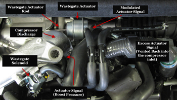
There are two means to electronically control the wastegate. One utilizes a solenoid, usually referred to as the wastegate solenoid, which is duty-cycled to prevent or redirect the actuator signal (boost pressure) going to the actuator diaphragm (see Figure 5).
Controlling the wastegate electronically and not relying solely on the mechanical pressure of a spring prevents the wastegate from prematurely cracking open as boost pressure rises, allowing the system to produce an optimum amount of boost without endangering the engine.
The other means utilizes an electric motor to directly drive the wastegate actuator rod (see Figure 6). Being electrically driven versus pneumatically driven allows the wastegate to open without boost pressure.
This increases the speed of producing maximum boost pressure by keeping the valve closed until needed to be opened, and allows the system to increase fuel efficiency by opening the valve to decrease pumping loss when boost is not needed. Additionally, the wastegate can be opened during cold starts to decrease catalytic converter light-off time.
 Vehicles equipped with an electronically controlled bypass valve also utilize the PCM to activate a solenoid, sometimes referred to as the bypass valve or surge valve solenoid (see Figure 7). Unlike the wastegate solenoid, the bypass valve solenoid is duty-cycled to control manifold vacuum. The bypass valve will not open until manifold vacuum is present at the valve’s diaphragm.
Service/Diagnostics
Servicing and maintaining turbocharged vehicles is very similar to working on naturally aspirated vehicles. However, with extremely high exhaust temperatures and a turbine shaft spinning up to several hundred thousand rounds per minute, maintaining the lubrication and cooling system is very important.
Technicians must be detailed in using the correct viscosity and types of oil specified for a particular vehicle, and abstain from mixing different types of coolant.
Furthermore, technicians should advise their customers to allow the turbocharger to spool down after hard driving or driving with a heavy load. This can be done by leaving the engine running for a minute or two before turning off the vehicle.
There are vehicles designed to stay running after the key is cycled off to allow the turbocharger to cool and spool down.
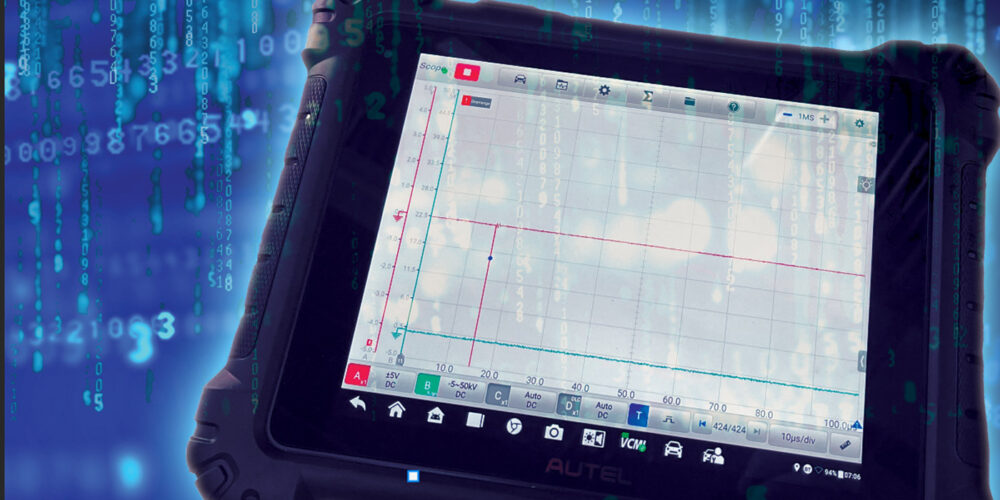
Technicians working on electronically controlled turbocharger systems can use a multiple channel digital storage oscilloscope and scan tool data to monitor and diagnose the system.
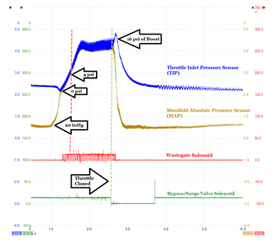
Figure 8 is a normal oscilloscope shot from a 2005 Dodge SRT-4 utilizing a MAP sensor, TIP sensor, wastegate solenoid and surge valve solenoid to control the turbocharger.
The scope shot illustrates how the wastegate solenoid starts to allow actuator signal (boost pressure) to reach the wastegate actuator diaphragm at around 4 psi of boost and the duty cycle of the wastegate solenoid increases with boost pressure.
As stated before, holding the actuator signal allows the turbocharger to build boost quicker by keeping the wastegate valve closed, preventing exhaust pressure from bypassing the turbine wheel. The actuator rod on this particular vehicle is designed to actuate the valve at 4 psi.
It is interesting to see how manifold pressure dramatically decreases, but the pressure between the compressor discharge and the throttle plate decreases at a slower rate (throttle inlet pressure).
In fact, the boost pressure actually increases after the throttle is closed and more so when the wastegate solenoid is turned off. This is due to the fact that, although decelerating, the engine and turbo are still spinning (spooling), producing pressure for several milliseconds after the throttle is closed.
Problems can occur when either one of the valves fails to function correctly. A wastegate that is stuck closed will cause an overboost problem and may cause turbo/engine damage, while a leaking or stuck open wastegate will decrease performance.
Wastegate problems on pneumatically actuated systems can easily be diagnosed by applying pressure to actuate the actuator. Likewise, a wastegate problem on an electric motor-driven system can be actuated using a scan tool.
Faulty bypass or surge valves can also damage the turbocharger or decrease performance. A misadjusted or seized closed bypass valve can cause surge, while a valve that is seized open will prevent the system from producing optimum boost pressures.
 Surge is unvented or excessive boost pressure that pushes back against the compressor wheel. This problem can cause damage to the turbocharger’s blades, shaft and bearings.
Most surge problems that are found on OE applications occur during closed throttle or as the engine decelerates. Surge that occurs during load are more dangerous due to the high pressures produced, but are not common with OE applications.
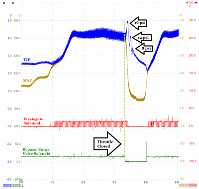
The scope shot on Figure 9 illustrates a slight surge during an abrupt closed throttle test. Although this particular problem was caused by an over-tightened bypass valve spring, a sticking bypass valve or a leaking vacuum hose can cause this problem as well.
As indicated, the pressure started to drop after the throttle was closed, but the pressure went back up because the bypass valve closed due to the over-tightened spring. The valve reopened after the pressure increased the second time and the whole cycle continued until all the boost pressure was fully dissipated.
What Is Next?
The use of turbochargers is a very efficient and effective way for manufacturers to produce engines that can meet the standards of both the consumer and government agencies. Just like most systems, it is now being electronically controlled. Therefore, technicians must understand how turbochargers are designed and
controlled to keep up with all the changes. As technology improves with twin scroll and variable geometry turbochargers (VGT), it is exciting to think about what will be next.
Special thanks to graduate assistant Alexander Richards, who contributed to this article.