It is a common mistake to look at a vehicle’s chassis and suspension system as just components that are either good, bad or broken. It should be looked at as a system. Understanding basic terminology and vehicle configurations is important to the technician for maintaining or returning that new car chassis control and performance.
It is also necessary to identify the basic suspension types and components before describing the dynamics of chassis control and their effects on vehicle performance. The goal is to have your customer say, “It rides like it did when it was new,” whether it be Luxury or Sport. Suspension engineers spend countless hours designing and tuning a suspension to the chassis to produce the ride and performance that is expected by the potential new car buyer. A modification to the chassis or suspension can have a significant effect on vehicle safety and performance.
The tire is the most important and perhaps the most overlooked component of the suspension. The four tire contact patches are the vehicle’s most important dimensions to safety and performance. Each tire has a contact patch that is its footprint on the road. The tire is a suspension component with the ability to absorb and dampen road impacts.
Passenger car and light truck radial tires are an active component of the suspension using the air as a spring and the side wall and tread surface as a shock absorber to dampen road surface irregularities. The profile, contact patch and pressure have a significant effect on the spring and damping properties of the tire. The wheel center locates the tire contact patch. The stamped steel or cast aluminum wheel’s width and offset affect the performance of the tire and its tread life.
Offset affects the scrub radius of the tire. As rim width increases and is moved outboard, it places a portion of the contact patch outside the scrub radius and will increase wear on that section of the tread. Rim width affects the contact patch. Tire manufacturers have a recommended rim width for a given tire size. The suspension locates the wheel and brake assembly. This assembly is in direct contact with the road surface and makes up unsprung mass of the suspension system.
Chassis/Frame/Body
The chassis can be either a frame and body or a uni-body. The construction of the chassis will locate the vehicle center of gravity or mass. The center of gravity or mass is one of the most important safety and performance factors in the design and construction of a vehicle.
Suspension
There are 16 types of suspensions in use today ranging from solid axles to struts. The suspension’s main job is to let the wheels move independently from the body.
One thing that almost all of them have in common are elastomer bushings. These soft parts of the suspension are used to dampen road shock before it is transferred to the chassis.
The friction created by the bushing’s position in the linkage has a dampening effect when the linkage moves around the bushing, just like the early friction shocks of the 1920s.
Springs
There are four types of springs used to suspend the mass of the vehicle: Air, Coil, Leaf and Torsion. The springs help to support the weight of the vehicle and absorb and releases energy. This energy is adsorbed by the shocks or struts.
Shock Absorber
There are two types of hydraulic valve shock absorbers — dual cylinder and mono tube. The dual cylinder has a piston and base valve. The piston has two sets of orifices and valves to meter fluid for the compression and rebound stroke of the shock.
The base valve is used to compensate for the displacement of fluid caused by the piston shaft movement in and out of the inner cylinder and meters fluid on the compression stroke of the shock. The outer tube acts as a reservoir for the fluid displaced by the shaft and its lower mounting. The upper mounting is attached to the shaft. The mono-tube shock uses a piston and pressurized chamber at the bottom of the shock to compensate for the displacement of fluid caused by the shaft. The piston valves are the same as the dual cylinder. The magnetorheological fluid shock is a mono-tube design with one set of orifices. The magnetic field generated by the coil in the piston will control fluid flow in both directions. The shock piston valves are tuned to the unsprung weight to dampen suspension travel.
The MacPherson Strut is a combination of a spring and shock absorber and upper mount that contains a bearing to allow the strut to rotate with the steering knuckle. An air strut uses a tapered sleeve type air spring to replace the coil spring.
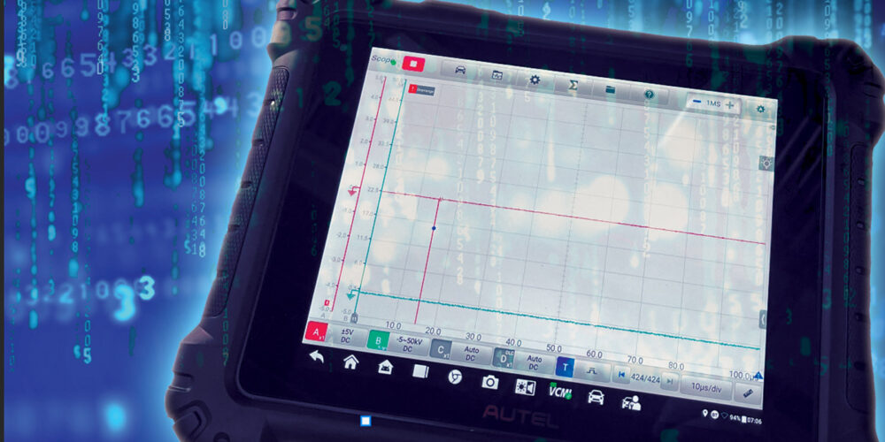
 Measuring Chassis Performance
Measuring chassis performance begins with the engineer and a computer model before the vehicle is built. The dynamics of the suspension and chassis are placed on a 3-dimensional set of axis based on the front of the vehicle. The X, Y and Z axis intersect at the center of gravity. The center of gravity is the point on the vehicle where you could place a jack and lift all four wheels and the vehicle would remain level. The Z or roll axis is at the centerline of the vehicle and passes from the rear suspension roll center to the front suspension roll center.
The Y or yaw axis is perpendicular to the Z axis. The X axis is on the same plane as the Z axis. The roll center is determined by the center point of the axle. In the case of an independent suspension, the center point is located between the two lower control arms.
Lateral Acceleration/Cornering
The steering angles generated by the knuckle and linkage are generally referred to as Ackerman steering angles. These angles are associated to low speed turning radius dimensions. As vehicle speed increases, steering angles tend to move forward toward the center of gravity. As a vehicle executes a cornering maneuver, the chassis is affected on the X, Y and Z axis. The X axis is a lateral acceleration that pushes the vehicle toward the outside of the corner. It is measured in “G”. G or Gravity is the attraction of a body toward the earth. The resting weight of a body on the surface is calculated as 1 G. The Z axis is affected by a rotational acceleration that would tip the vehicle toward the outside of the corner. It would be measured in degrees per second. As the rear, wheel slip angle increases, it causes the chassis to rotate at its center of gravity.
The faster the corner, the more the chassis will tend to roll. During a cornering maneuver, entire weight distribution of the vehicle changes. In a right hand corner, the most weight is placed on the left front wheel.
The right rear wheel carries the least amount of weight. If the vehicle is breaking in the corner, even more weight is shifted to the left front wheel. Chassis roll is determined by an axis running from the rear roll center to the front roll center of the vehicle. The Z axis determines the rotation of the chassis during a corner. The inclination of the chassis and center of mass of a vehicle determine how much chassis roll will occur during a corner.
Acceleration and Deceleration
Acceleration and deceleration causes a rotation around the X axis or pitch replaces dive and squat. Dive was used to describe vehicle attitude during a deceleration or braking and pitch was used to describe acceleration.
The center of gravity and its mass affects the amount of vehicle pitch during an acceleration or deceleration. The location of the suspension linkages and axles are designed to minimize these rotational forces. As an example, changing the mounting angle of an upper control, arm or MacPherson strut can reduce the amount of pitch during a deceleration or stop.
The extremes of vehicle construction can best demonstrate how the roll center and center of gravity or mass affects chassis roll. The Corvette is a performance vehicle designed for high-speed cornering. It has a roll center that is parallel and close to ground level as possible. Its center of mass is very close to the roll center and is located in the center of the vehicle. This produces an almost neutral position during high-speed corners.
The ground clearance of the Corvette is minimal, as it is to be driven on maintained paved surfaces. A van is a utility vehicle designed to transport passengers and cargo and its ground clearance is much greater. Its roll center axis is on an incline as the roll center of the rear axle is higher than the control arms of the independent front suspension.
Its center of mass is toward the front of the vehicle and can change based on how the vehicle is loaded. The suspension of the van will receive more stress under normal service than those in the Corvette.